On-board vertical-fin conformal omnidirectional antenna

An omnidirectional antenna and vertical tail cavity technology, which is applied in the electrical field, can solve the problems of inability to realize, the performance of the omnidirectional antenna has a great influence, and the application of the vertical tail conformal antenna is limited, and achieves stable performance, optimized aerodynamic performance, and structural simple effect

Pending Publication Date: 2018-02-23
上海龙华汽车配件有限公司
View PDF0 Cites 3 Cited by
  • Summary
  • Abstract
  • Description
  • Claims
  • Application Information

AI Technical Summary

Problems solved by technology

[0002] Airborne communication antennas used in aircraft are required to work omnidirectionally in the horizontal plane. In the prior art, the airborne communication antennas are basically exposed to the carrier. The advantage of this airborne method is that the antenna can easily achieve omnidirectional operation, but the antenna needs to protrude carrier, destroying the aerodynamic performance of the carrier aircraft
Omni-directional antennas can adopt low-profile conformal airborne methods after technical improvement, but there are strict requirements on the size, strength and environmental adaptability of the antennas, and it is impossible to make the carrier air without changing the original shape of the carrier. Optimum dynamic performance
At the same time, antennas that conform to the vertical tail of the aircraft are currently used, but there are structural metal parts that increase the strength built into the vertical tail. These structural metal parts have a great impact on the performance of the omnidirectional antenna, especially the radiation pattern. The carrier antenna cannot effectively work omnidirectionally in the horizontal plane, which greatly limits the application of this type of vertical tail conformal antenna

Method used


Image

  • On-board vertical-fin conformal omnidirectional antenna
  • On-board vertical-fin conformal omnidirectional antenna
  • On-board vertical-fin conformal omnidirectional antenna

Examples


Embodiment 1

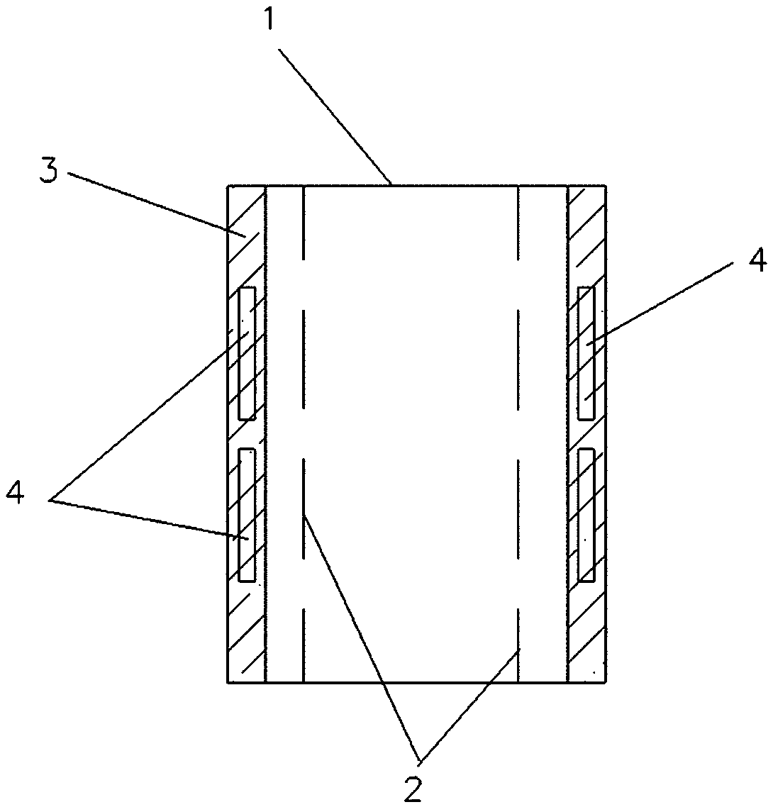
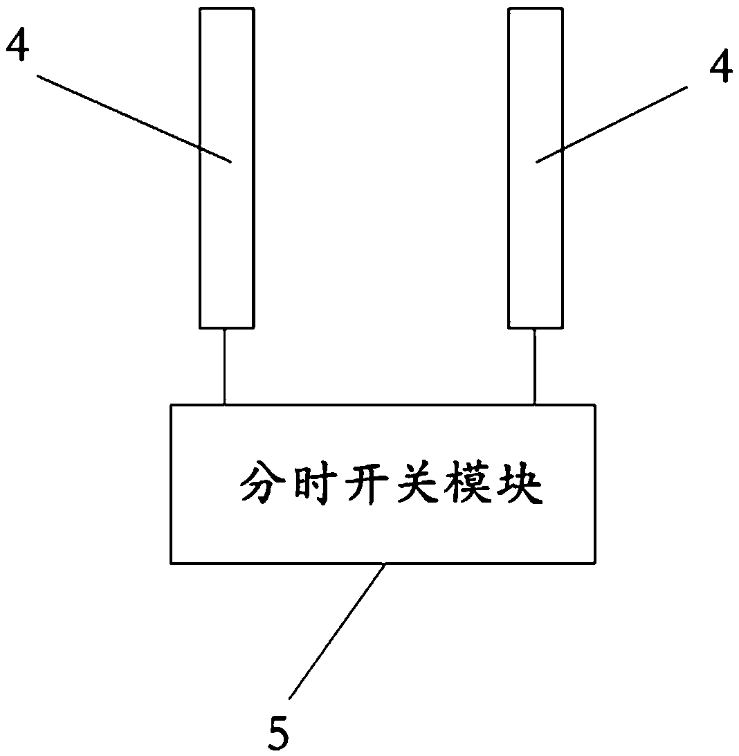
[0014] Such as Figures 1 to 3 As shown, this airborne vertical tail conformal omnidirectional antenna of the patent of the present invention includes an aircraft vertical tail 1 and an omnidirectional antenna 4, the omnidirectional antenna 4 is arranged in the surface skin 3 of the aircraft vertical tail 1, and the omnidirectional antenna 4 It is a group correspondingly arranged on both sides of the structural metal part 2 in the cavity of the vertical tail 1 of the aircraft. The omnidirectional antenna 4 is electrically connected to the time-sharing switch module 5. The time-sharing switch module 5 can produce milliseconds to nanoseconds according to the general requirements of communication. The time-sharing control signal between them is used to control the omnidirectional antenna to work alternately in time-sharing to generate a horizontal omnidirectional pattern.

[0015] Further, the omnidirectional antenna 4 and the skin 3 are integrally formed so that the omnidirectio...


PUM


Abstract

An airborne vertical tail conformal omnidirectional antenna, including an aircraft vertical tail and an omnidirectional antenna, the omnidirectional antenna is arranged in the surface skin of the aircraft vertical tail, and the omnidirectional antenna is a group of structural metals correspondingly arranged in the aircraft vertical tail cavity On both sides of the component, the omnidirectional antenna is electrically connected to the time-sharing switch module, and the time-sharing switch module is used to control the omnidirectional antenna to work alternately in time. The airborne omnidirectional antenna forms a conformal structure by setting the antenna in the vertical tail of the aircraft, and uses a time-sharing switch module to control a group of omnidirectional antennas to work alternately at the same time, which realizes the optimization of the aerodynamic performance of the airborne antenna and the overall stability of the antenna. Directional working mode, simple structure and stable performance.

Description

technical field [0001] The invention relates to the field of electricity, in particular to communication technology, in particular to antenna technology, in particular to an airborne vertical tail conformal omnidirectional antenna. Background technique [0002] Airborne communication antennas used in aircraft are required to work omnidirectionally in the horizontal plane. In the prior art, the airborne communication antennas are basically exposed to the carrier. The advantage of this airborne method is that the antenna can easily achieve omnidirectional operation, but the antenna needs to protrude carrier, destroying the aerodynamic performance of the carrier aircraft. Omni-directional antennas can adopt low-profile conformal airborne methods after technical improvement, but there are strict requirements on the size, strength and environmental adaptability of the antennas, and it is impossible to make the carrier air without changing the original shape of the carrier. The d...

Claims


Application Information

Patent Timeline
Patent Type & Authority Applications(China)
IPC IPC(8): H01Q1/22H01Q1/28H01Q1/36H01Q1/50
CPCH01Q1/50H01Q1/22H01Q1/285H01Q1/36
Inventor 王学杰
Owner 上海龙华汽车配件有限公司
Why Eureka
Try Eureka