Strain clamp

A technology of tension clamp and clamp plate, applied in the direction of adjusting/maintaining mechanical tension, optical fiber/cable installation, cable suspension device, etc., to achieve the effect of improving work efficiency and not easy to adjust deviation

Inactive Publication Date: 2018-02-23
张龙兵
View PDF0 Cites 3 Cited by
  • Summary
  • Abstract
  • Description
  • Claims
  • Application Information

AI Technical Summary

Problems solved by technology

[0003] The present invention overcomes the deficiencies of the prior art, provides a strain-resistant clamp, can quickly align and clamp the first clamping board and the second clamping board, and is not prone to misalignment, greatly improving work efficiency

Method used


Image

  • Strain clamp

Examples


Embodiment 1

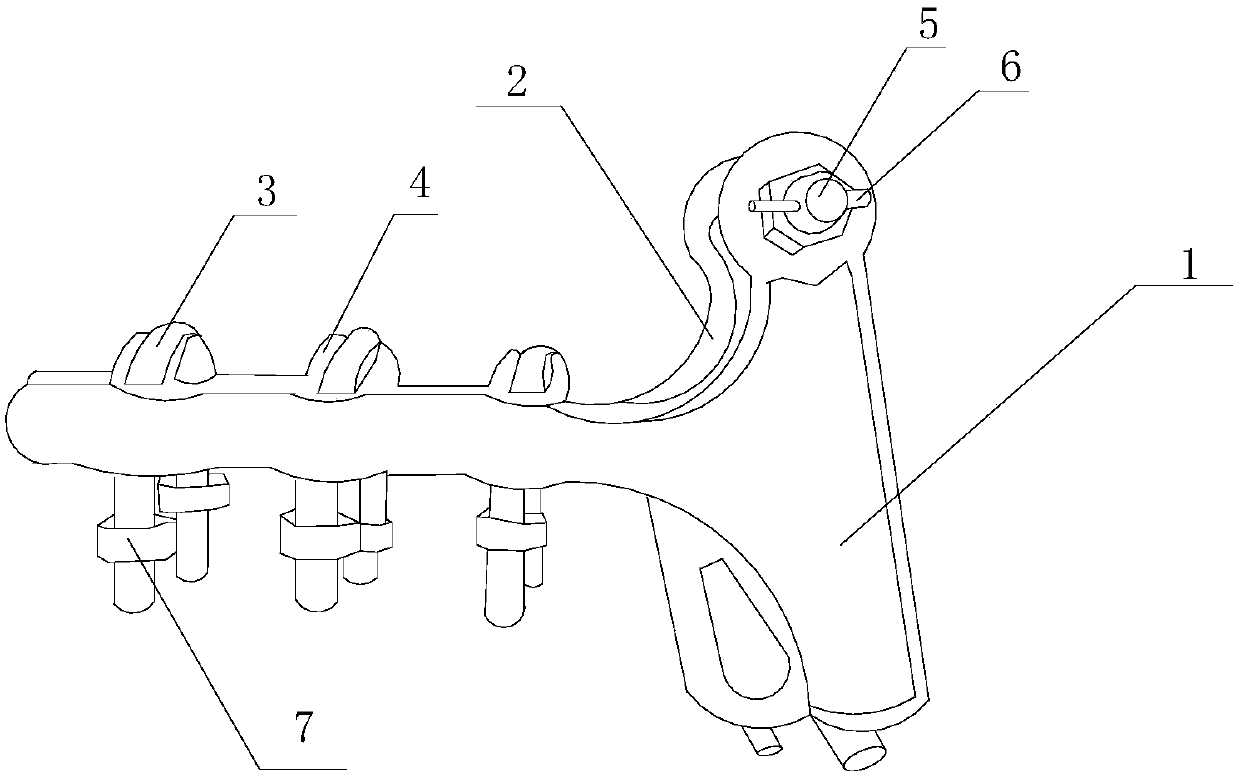
[0015] Such as figure 1 As shown, the present invention includes a strain-resistant clamp, including a first line clamping plate 1 and a second line clamping plate 2, and the first line clamping plate 1 and the second line clamping plate 2 both include horizontal plates and vertical plates. The vertical plates of the first line clamping plate 1 and the second line clamping plate 2 vertically cross the connecting rod 5, and also cross the limit rod 6 on the end face of the connecting rod 5, on the first line clamping plate 1 and the second clamping plate A plurality of limiting grooves 4 are arranged between the horizontal plates of the line plate 2, and an n-type limiting member 3 is installed in each limiting groove 4, and a bolt 7 is sleeved on the bottom of the n-type limiting member 3.

[0016] When it is necessary to fix the wires, loosen the bolts at the bottom of all n-type limiters, put the wires into the cavity formed by the first clamping plate and the second clampin...

Embodiment 2

[0018] This embodiment is preferably as follows on the basis of Embodiment 1: the bottoms of the first wire clamping plate 1 and the second wire clamping plate 2 are also provided with threading holes. Easy to carry out threading operation.

[0019] The edge portions of the vertical plates of the first line clamping plate 1 and the second line clamping plate 2 are also provided with drainage grooves. The drainage groove is used to quickly drain the rainwater that falls on it, so as to prevent the rainwater from staying on it for a long time and corroding the device.

[0020] Two guard plates for protecting the n-type limiting member 3 are arranged on each limiting groove 4 . The n-type limiter is protected inside to avoid unnecessary falling off of the n-type limiter due to external force.

[0021] Both ends of the first wire clamping plate 1 and the second wire clamping plate 2 are arranged in an arc-shaped structure. Avoid scratching other parts.


PUM


Abstract

The invention discloses a strain clamp, which includes a first wire clamping plate and a second wire clamping plate, both of which include a horizontal plate and a vertical plate, and the first wire clamping plate and the second wire clamping plate The vertical plate of the second clamping plate vertically traverses the connecting rod, and also traverses the limit rod on the end face of the connecting rod, and sets a plurality of limit positions between the horizontal plates of the first clamping plate and the second clamping plate slot, an n-type limiting piece is installed in each limiting groove, and a bolt is sleeved at the bottom of the n-type limiting piece. Through the above-mentioned structure, the present invention can quickly align and fasten the first line clamping board and the second line clamping board, so that deviation adjustment is not easy to occur, and the work efficiency is greatly improved.

Description

technical field [0001] The invention relates to the field of electric fittings, in particular to a strain clamp. Background technique [0002] Strain clamps are mainly used for fixing aluminum stranded wires and steel-cored aluminum stranded wires on the tension towers of overhead lines and substations. Strain clamps are used for corners, splices, and terminal connections. The spiral aluminum-clad steel wire has extremely strong tensile strength, and the tension clamp has no concentrated stress, which can protect and assist the vibration reduction of the optical cable. A complete set of cable tension fittings includes: tension pre-twisted wire, supporting connection fittings. The holding force of the cable clamp is not less than 95% of the rated tensile strength of the optical cable, which is convenient and fast to install and reduces the construction cost. According to different structures and installation conditions, strain clamps can be roughly divided into two categor...

Claims


Application Information

Patent Timeline
Patent Type & Authority Applications(China)
IPC IPC(8): H02G7/02H02G7/05G02B6/46
CPCH02G7/02G02B6/46H02G7/05
Inventor 张龙兵
Owner 张龙兵
Why Eureka
Try Eureka