Cast-in-situ concrete hollow board

A technology of hollow slab and cast-in-place concrete, which is applied in the direction of floors, building components, buildings, etc., can solve the problems affecting the construction quality of hollow slabs, affecting the construction quality of slabs, and not being able to arrange hollow carcass. Excellent vibration performance and fast construction speed

Inactive Publication Date: 2007-08-01
湖南邱则有专利战略策划有限公司
View PDF3 Cites 2 Cited by
  • Summary
  • Abstract
  • Description
  • Claims
  • Application Information

AI Technical Summary

Problems solved by technology

But when this kind of hollow carcass is applied to the floor construction, the hollow carcass cannot be accurately arranged in the middle layer of the floor, which affects the construction quality of the floor
For this reason, the patent number is ZL01215092.4, and the utility model patent titled "Building Components" discloses a building component that is a polyhedron, which can be hollow or solid. It is arranged in the middle layer of the floor, and the outer wall of the polyhedron is provided with protruding legs, so that when the floor is poured, the legs can ensure that the hollow multi-faceted main cavity is just at the middle layer of the floor. , so as to better solve the above problems. However, the positioning of this building component is inconvenient during construction and layout, and it is prone to misalignment, which affects the construction quality of the hollow floor and affects the construction efficiency. Therefore, a new type of existing Concrete hollow slabs are urgently needed

Method used


Image

  • Cast-in-situ concrete hollow board
  • Cast-in-situ concrete hollow board
  • Cast-in-situ concrete hollow board

Examples


Embodiment Construction

[0077] The present invention will be further described below in conjunction with the accompanying drawings and embodiments.

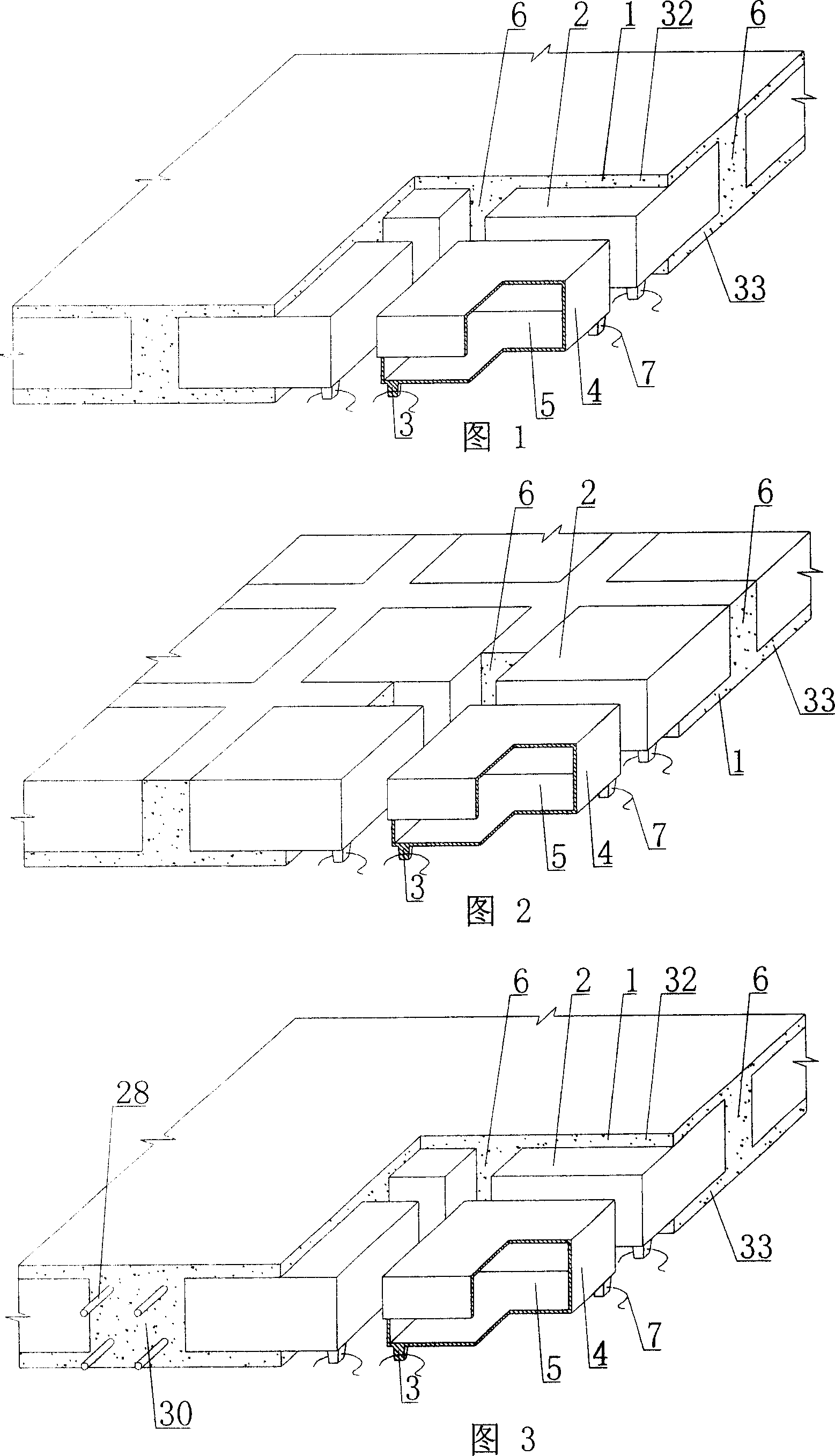
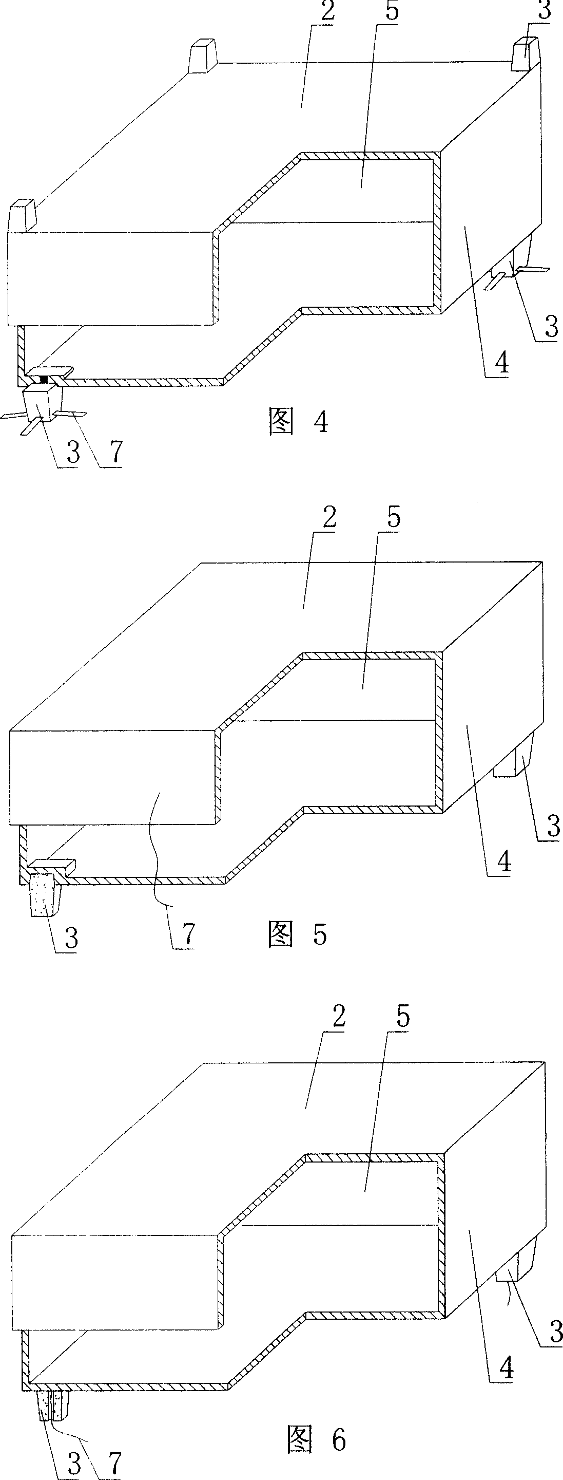
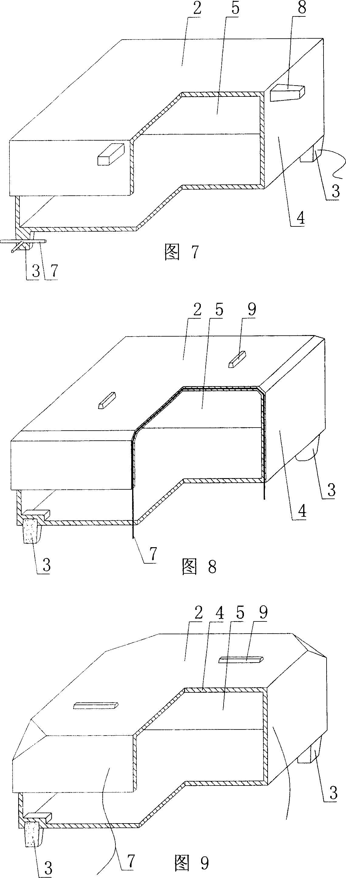
[0078] As shown in the accompanying drawings, the present invention includes a reinforced concrete 1 and a hollow carcass 2, the hollow carcass 2 is wrapped in the reinforced concrete 1, the bottom outer wall 4 of the hollow carcass 2 is provided with a support foot 3, and the outer wall 4 is enclosed to form A hollow carcass 2 with a cavity 5, and the hollow carcass 2 are cast-in-place reinforced concrete ribs 6 formed by reinforced concrete 1, which is characterized in that the hollow carcass 2 or / and the support feet 3 are provided with fixed Or split positioning anti-floating member 7. In each drawing, 1 is reinforced concrete, 2 is hollow carcass, 3 is support foot, 4 is outer wall, 5 is cavity, 6 is cast-in-place reinforced concrete rib, 7 is positioning anti-floating parts, in the following drawings , with the same number, the description is the...


PUM


Abstract

Disclosed is a cast-in-situ concrete hollow slab, which comprises a reinforced-bar concrete (1) and hollow blank members (2), the hollow blank members (2) are enclosed in the reinforced-bar concrete (1), the hollow tire body (2) is provided with a bracing strut (3), the outer wall (4) encloses the hollow tire body (2) formed with a cavity (5), cast-in-situ reinforced bar concrete ribs (6) formed by the reinforced-bar concrete (1) are disposed between the hollow tire bodies (2), characterized in that the hollow carcass (1) or/and bracing strut (2) is provided with a fixed or split anti-floating and positioning member (7). The invention can be applied to cast-in-situ reinforced concrete or prestressed reinforcement concrete's hollow storied-building roofings, house roofings, walls, foundation bedplates and bridges, especially for hollow flat slabs.

Description

(1) Technical field [0001] The invention relates to a cast-in-place concrete hollow slab. (2) Background technology [0002] At present, the cast-in-place concrete hollow floor is a widely used floor structure. The lightweight permanent tire molds filled in it include various hollow tubes and boxes, and the boxes are hollow or solid. For example, the patent No. ZL99249798.1, which the applicant applied for on November 29, 1999, is a utility model patent named "fiber-reinforced thin-walled member for reinforced concrete filling", which discloses a thin-walled formwork member, including an upper plate, The surrounding side walls, the lower bottom, and the upper plate, the surrounding side walls and the lower bottom form a polyhedral cavity. Another example is that the patent No. is ZL00203695.9, and the name is called "combined concrete hidden rib floor slab" utility model patent, which discloses a formwork member in its specification, which can be solid or hollow, and its sh...

Claims


Application Information

Patent Timeline
Patent Type & Authority Applications(China)
IPC IPC(8): E04B5/18E04B5/36
Inventor 邱则有
Owner 湖南邱则有专利战略策划有限公司
Why Eureka
Try Eureka