Method and device of assembling components, considering the relative spatial position ifnormation

A technology of relative space and components, applied in the direction of electrical components, electrical components, etc., can solve the problems of unfavorable and time-consuming waiting for vibration, and achieve the effect of eliminating waiting time, low cost, and improving accuracy

Active Publication Date: 2018-02-23
ASM ASSEMBLY SYST GMBH & CO
View PDF3 Cites 2 Cited by
  • Summary
  • Abstract
  • Description
  • Claims
  • Application Information

AI Technical Summary

Problems solved by technology

[0004] The problem with this is that this image capture is time-consuming and the waiting time has to be factored into the planning of the assembly process
Here, waiting for the damping of the vibration is the most unfavorable

Method used


Image

  • Method and device of assembling components, considering the relative spatial position ifnormation
  • Method and device of assembling components, considering the relative spatial position ifnormation
  • Method and device of assembling components, considering the relative spatial position ifnormation

Examples


Embodiment Construction

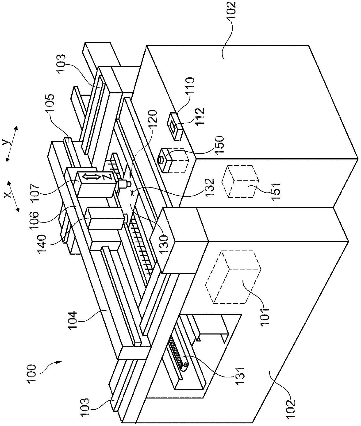
[0098] The same or similar parts are indicated by the same reference signs in the drawings.

[0099] According to the embodiment, when the component is measured on-the-fly in an automatic assembly machine, the following restrictions must be overcome when applying the method: i) The measurement accuracy is affected by the difference between the camera and the component. Physical effects such as vibration; ii) Position synchronization between the driver of the assembly head and the display system (ie camera). In principle, this method can also optimize today's pick and place processes in terms of time. Because the position and angle-reference are obtained directly through the component-holding device (especially the straw), there is no need to wait for the stop time.

[0100] According to another embodiment, suitable markings are provided on the component-holding device (especially the straw). They can for example be designed as a surrounding circle to form a side reference. Set a...


PUM


Abstract

The invention relates to a method of mounting components for component carriers by means of an automatic assembly machine. The method includes the steps: i) removing the component from at least one component-supply device by means of a component-clamping device, wherein the component is at least temporarily connected with the connection structure of the component-clamping device; ii) transmittingthe at least one removed component to the assembly area of the automatic assembly machine; iii) performing optical detection on the image of the mark, relatively arranged on the component-clamping device by means of a camera, and performing optical detection on the image of the component which is connected with the component-clamping device temporarily; iv) evaluating the detected image by means of a data processing unit connected downstream of the camera to obtain the information of the relative spatial position between the component and the component-clamping device; and v) taking into account of the information about the relative spatial position between the component and the component-clamping device, and assembling the component onto the component carrier.

Description

Technical field [0001] The present invention relates to the technical field of electronic component manufacturing. The present invention particularly relates to a method and a component-holding device for giving components by means of an automatic assembly machine, taking into account the information about the relative spatial position between the component and the component-holding device Carrier assembly components. In addition, the present invention also relates to an automatic assembly machine for automatically assembling components to a component carrier, and also relates to a computer program. Background technique [0002] Usually electronic components and circuits with electronic components are mounted on one or more component carriers (such as printed circuit boards (PCBs). The manufacturing process of electronic components usually includes assembling components to the component carriers. The components are arranged on the surface of the component carrier, Called "Surfa...

Claims


Application Information

Patent Timeline
Patent Type & Authority Applications(China)
IPC IPC(8): H05K13/04H05K13/08
CPCH05K13/0404H05K13/08H05K13/0409H05K13/0813
Inventor 贝希·卡尔-海因茨特赖贝尔·马尔科
Owner ASM ASSEMBLY SYST GMBH & CO
Why Eureka
Try Eureka