A miniaturized functional fiber drawing equipment

A technology of functional fiber and equipment, which is applied in the field of miniaturized functional fiber drawing equipment, can solve problems such as the inability to meet the flexibility and diversity of optical fibers, and achieve the effect of simple configuration, less material consumption and high flexibility

Active Publication Date: 2020-07-10
HUAZHONG UNIV OF SCI & TECH
View PDF2 Cites 0 Cited by
  • Summary
  • Abstract
  • Description
  • Claims
  • Application Information

AI Technical Summary

Problems solved by technology

[0005] In view of the defects of the prior art, the purpose of the present invention is to provide a miniaturized functional fiber drawing equipment, which aims to solve the problem that the existing industrial-grade or experimental optical fiber drawing equipment cannot meet the flexible and diverse requirements for optical fibers

Method used


Image

  • A miniaturized functional fiber drawing equipment
  • A miniaturized functional fiber drawing equipment
  • A miniaturized functional fiber drawing equipment

Examples


Embodiment 1

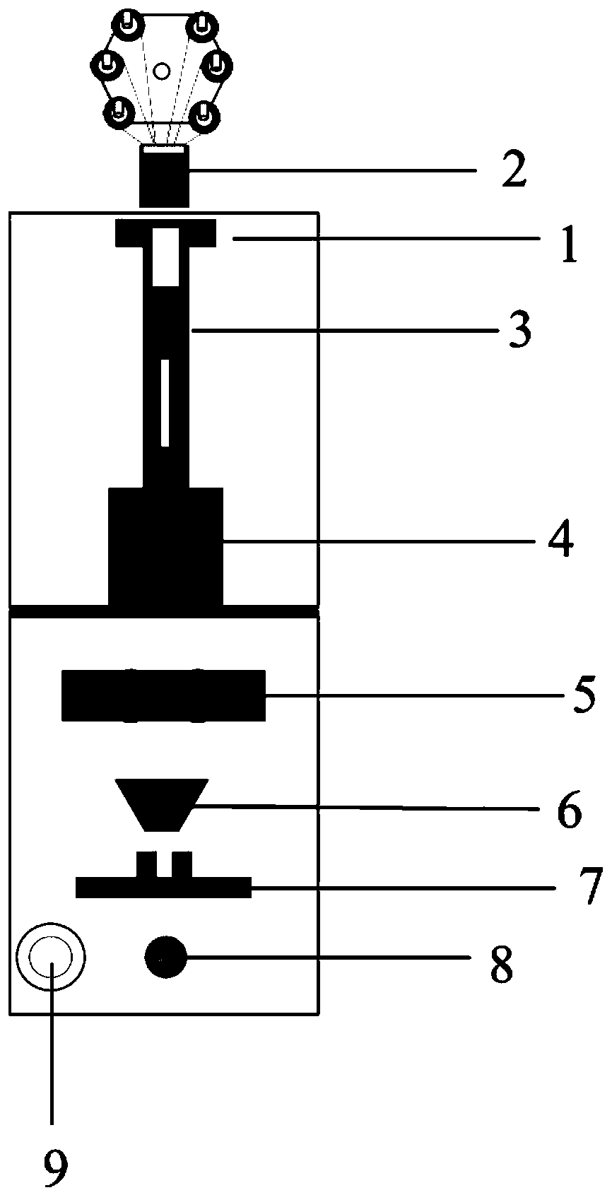
[0049] The functional fiber drawing equipment provided in this embodiment includes a metal frame 1 , a rod feeding device 3 , a heating furnace 4 , an auxiliary traction device 5 , a diameter measuring device 7 , a guide wheel 8 and a wire take-up device 9 .

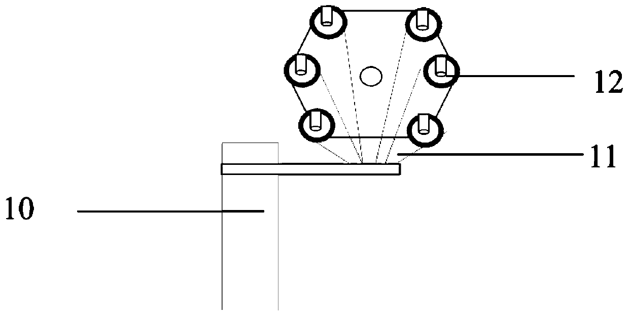
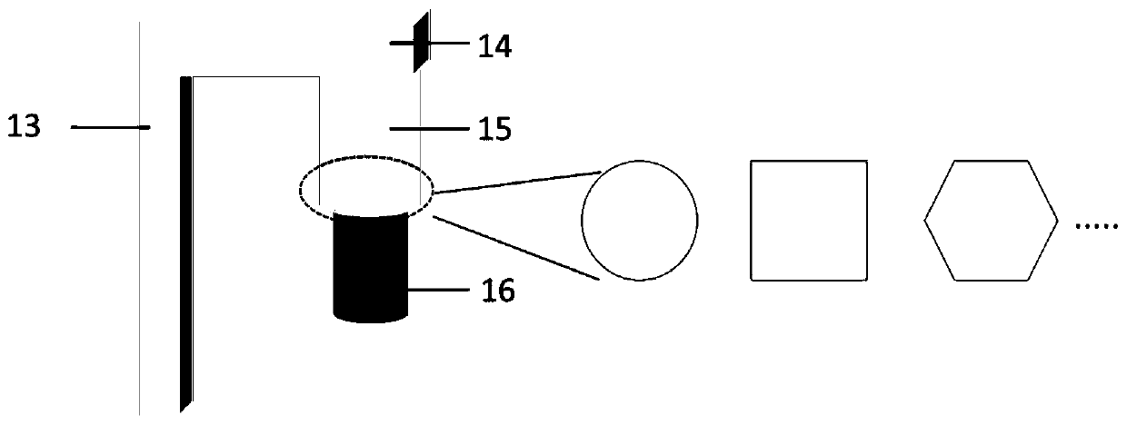
[0050] The rod feeding device 3 consists of three parts: a mechanical sliding track 13, a metal tail handle 14 and a chuck sleeve 15, the mechanical sliding track 13 is fixed on the top of one side of the metal frame 1, and one end of the metal tail handle 14 is fixed on the mechanical sliding track 13 , the metal tail handle 14 can be driven by a servo motor to slide vertically up and down on the mechanical sliding track 13, and the other end of the metal tail handle 14 is fixed with a chuck sleeve 15 of the preform rod. The chuck sleeve 15 is circular in shape, and one section of the chuck sleeve 15 adopts a top wire to lock the preform. The diameter of the collet sleeve 15 is 35 mm, which can hold the preform rod with...

Embodiment 2

[0053] The functional fiber drawing equipment provided in this embodiment includes a metal frame 1 , a rod feeding device 3 , a heating furnace 4 , an auxiliary traction device 5 , a diameter measuring device 7 , a guide wheel 8 and a wire take-up device 9 .

[0054] The rod feeding device 2 consists of three parts: a mechanical sliding track 13, a metal tail handle 14 and a collet sleeve 15, the mechanical sliding track 13 is fixed on the top of one side of the metal frame 1, and one end of the metal tail handle 14 is fixed on the mechanical sliding track 13 , the metal tail handle 14 can be driven by a servo motor to slide vertically up and down on the mechanical sliding track 13, and the other end of the metal tail handle 14 is fixed with a chuck sleeve 15 of the preform rod. The chuck sleeve 15 is circular in shape, and one section of the chuck sleeve 15 adopts a top wire to lock the preform. The diameter of the collet sleeve 15 is 15 mm, which can hold the preform rod wit...

Embodiment 3

[0058] The functional fiber drawing equipment provided in this embodiment includes a metal frame 1 , a rod feeding device 3 , a heating furnace 4 , an auxiliary pulling device 5 , a coating device 6 , a diameter measuring device 7 , a guide wheel 8 and a wire take-up device 9 .

[0059] The rod feeding device 2 consists of three parts: a mechanical sliding track 13, a metal tail handle 14 and a collet sleeve 15, the mechanical sliding track 13 is fixed on the top of one side of the metal frame 1, and one end of the metal tail handle 14 is fixed on the mechanical sliding track 13 , the metal tail handle 14 can be driven by a servo motor to slide vertically up and down on the mechanical sliding track 13, and the other end of the metal tail handle 14 is fixed with a chuck sleeve 15 of the preform rod. The chuck sleeve 15 is circular in shape, and one section of the chuck sleeve 15 adopts a top wire to lock the preform. The diameter of the collet sleeve 15 is 35 mm, which can hold...


PUM

PropertyMeasurementUnit
thicknessaaaaaaaaaa
heightaaaaaaaaaa

Abstract

The invention discloses miniature functional fiber wire drawing equipment which comprises a metal framework, a rod conveying device, a heating furnace, an auxiliary traction device, a diameter measuring device, a wire guide wheel and a wire collecting device, wherein the top end of the metal framework is provided with the rod conveying device; the right lower end of the rod conveying device is provided with the heating furnace; the right lower end of the heating furnace is provided with the auxiliary traction device; the right lower end of the auxiliary traction device is provided with the diameter measuring device; the right lower end of the diameter measuring device is provided with the wire guide wheel; the wire guide wheel is connected with the wire collecting device; the rod conveyingdevice is used for conveying prefabricated rods in different shapes; the heating furnace is provided with a plurality of heating intervals; the temperature is controlled in different intervals; the prefabricated rod realizing the free combination of the heating intervals and used for heating different materials is obtained. The functional fiber wire drawing equipment provided by the invention hasthe advantages that through optimizing the design of the heating furnace, and by aiming at different functional fiber requiring fine wire embedment or coating at the same time, a wire conveying coildevice and a coating device are respectively designed; various requirements in the functional fiber preparation process are met; the flexibility of the wire drawing equipment is high.

Description

technical field [0001] The invention belongs to the field of optical fiber equipment, and more specifically relates to a miniaturized functional fiber drawing equipment. Background technique [0002] Optical fibers are widely used in communication, laser transmission, sensing and other fields, and play an increasingly important role in human life. Optical fiber is usually produced by first preparing a preform, and then drawing the preform into an optical fiber through an optical fiber drawing device. At present, optical fiber drawing equipment has problems such as bulky size and high environmental requirements, and the materials that can be drawn by each drawing tower are relatively fixed. This has great limitations for us to study the regulation of multi-material fiber structure, morphology or performance, and to tap the potential power of optical fiber preparation technology. [0003] In practice, the demand for optical fibers for a single scientific research is very low...

Claims


Application Information

Patent Timeline
Patent Type & Authority Patents(China)
IPC IPC(8): C03B37/03C03B37/029C03B37/027C03B37/025B21C1/02B29C55/00
CPCB21C1/02B29C55/00C03B37/025C03B37/027C03B37/029C03B37/032C03B2205/62
Inventor 陶光明李攀
Owner HUAZHONG UNIV OF SCI & TECH
Why Eureka
Try Eureka