A kind of oil-gas-water horizontal three-phase separator and oil-gas-water separation method

A technology for three-phase separator and oil-water separation, which is applied in separation methods, chemical instruments and methods, liquid separation, etc., can solve the problem that the oil phase contains large-diameter water droplets, etc., so as to facilitate oil-water separation, promote oil-water separation, and improve The effect of the separation effect

Active Publication Date: 2019-12-17
SINOPEC GUANGZHOU ENG CO LTD +1
View PDF7 Cites 2 Cited by
  • Summary
  • Abstract
  • Description
  • Claims
  • Application Information

AI Technical Summary

Problems solved by technology

[0003] The purpose of the present invention is to provide a kind of oil-gas-water horizontal three-phase separator and oil-gas-water separation method, to solve the existing oil-gas-water horizontal three-phase separator separation of low gas-liquid ratio oil-gas-water mixture separated oil Phases tend to contain larger diameter water droplets

Method used


Image

  • A kind of oil-gas-water horizontal three-phase separator and oil-gas-water separation method
  • A kind of oil-gas-water horizontal three-phase separator and oil-gas-water separation method

Examples


Embodiment Construction

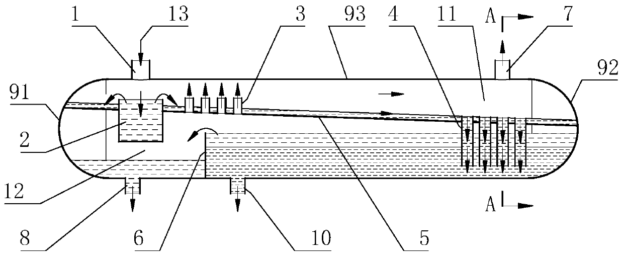
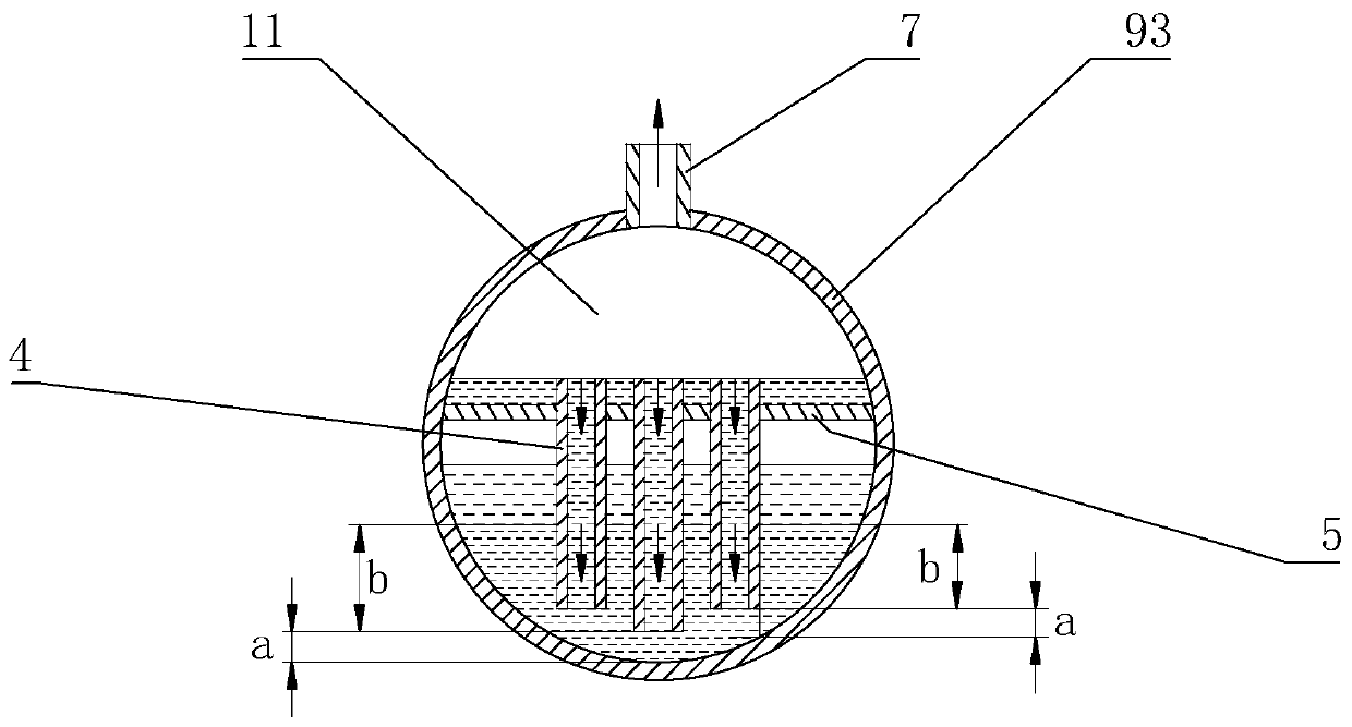
[0012] see figure 1 and figure 2 , the oil-gas-water horizontal three-phase separator (abbreviated as separator) of the present invention is provided with a horizontal tank body, the horizontal tank body includes a cylindrical body 93 and a first sealing head 91 and a second sealing head 92, two The heads are generally hemispherical. The bottom of the inner cavity of the cylindrical body 93 is vertically provided with an overflow plate 6, and the top of the cylindrical body 93 is provided with an inlet pipe 1 near the first head 91 and an outlet pipe 7 near the second head 92. The bottom of the cylindrical body 93 is provided with an oil outlet pipe 8 between the overflow plate 6 and the first head 91, and an outlet pipe 10 is provided between the overflow plate 6 and the second end head 92. The outlet pipe 10 is usually Close to overflow plate 6. The various pipes mentioned in the present invention generally have a circular cross-sectional shape.

[0013] The inner cavit...


PUM


Abstract

The invention discloses an oil-gas-water horizontal three-phase separator and an oil-gas-water separation method. The separator is provided with a horizontal tank body, and the inner cavity of the horizontal tank body is provided with a partition plate (5). A buffer (2) is arranged below an inlet pipe (1) on the partition plate, a downcomer (4) is arranged in the lower direction of an escape pipe(7), and a standpipe (3) is arranged between the buffer and the downcomer upwards. The portion positioned above an upper liquid layer of the partition plate inside the inner cavity of the horizontal tank body is a gas phase area (11), the portion positioned below the partition plate and between an overflow plate (6) and a second end socket (92) is an oil-water separation area, and the portion positioned below the partition plate and between the overflow plate and a first end socket (91) is an oil phase area (12). The invention discloses a method for carrying out oil-gas-water separation by adopting the oil-gas-water horizontal three-phase separator. The separator is mainly used for separation of an oil-gas-water mixture with low vapor liquid ratio in the field of oil and gas field oil gastreatment or other fields.

Description

technical field [0001] The invention relates to an oil-gas-water horizontal three-phase separator and an oil-gas-water separation method used in the technical field of oil and gas treatment in oil and gas fields. Background technique [0002] An existing oil-gas-water horizontal three-phase separator is provided with a horizontal tank body, which includes a cylindrical body and two end caps. The cylindrical body is provided with an inlet pipe, an oil outlet pipe, an air outlet pipe and a water outlet pipe, and the inner cavity of the tank body is provided with internal components such as an overflow plate and an inlet diverter. After the oil-gas-water mixture enters the three-phase separator, the inlet splitter initially separates the oil-gas-water mixture into gas-liquid two-phase. The separated liquid phase (including oil phase and water phase) enters the liquid collection area, and relies on the oil-water density difference to separate the oil and water, while the air bu...

Claims


Application Information

Patent Timeline
Patent Type & Authority Patents(China)
IPC IPC(8): B01D19/00B01D17/02B01D17/028B01D17/032
CPCB01D17/02B01D17/0211B01D17/0214B01D19/0042
Inventor 王以斌李文龙史纪元王文昊李战杰何龙辉李津王惠勤杜富国
Owner SINOPEC GUANGZHOU ENG CO LTD
Why Eureka
Try Eureka