Sand and stone filtering device for oil production

A filter device, sand and stone technology, applied in the direction of filtration separation, filtration circuit, only multi-stage series refining process, etc., can solve the problems of low filtration efficiency, incomplete filtration, unclean filtration, etc.

Pending Publication Date: 2018-02-27
魏文福
View PDF6 Cites 7 Cited by
  • Summary
  • Abstract
  • Description
  • Claims
  • Application Information

AI Technical Summary

Problems solved by technology

[0006] In order to overcome the disadvantages of low filtration efficiency, unclean filtration and incomplete filtration of the current petroleum sand filtration equipment, the technical problem to be solved by the present invention is to provide a high filtration efficiency, clean and thorough filtration of sand and stone for petroleum exploitation. filter device

Method used


Image

  • Sand and stone filtering device for oil production
  • Sand and stone filtering device for oil production
  • Sand and stone filtering device for oil production

Examples


Embodiment 1

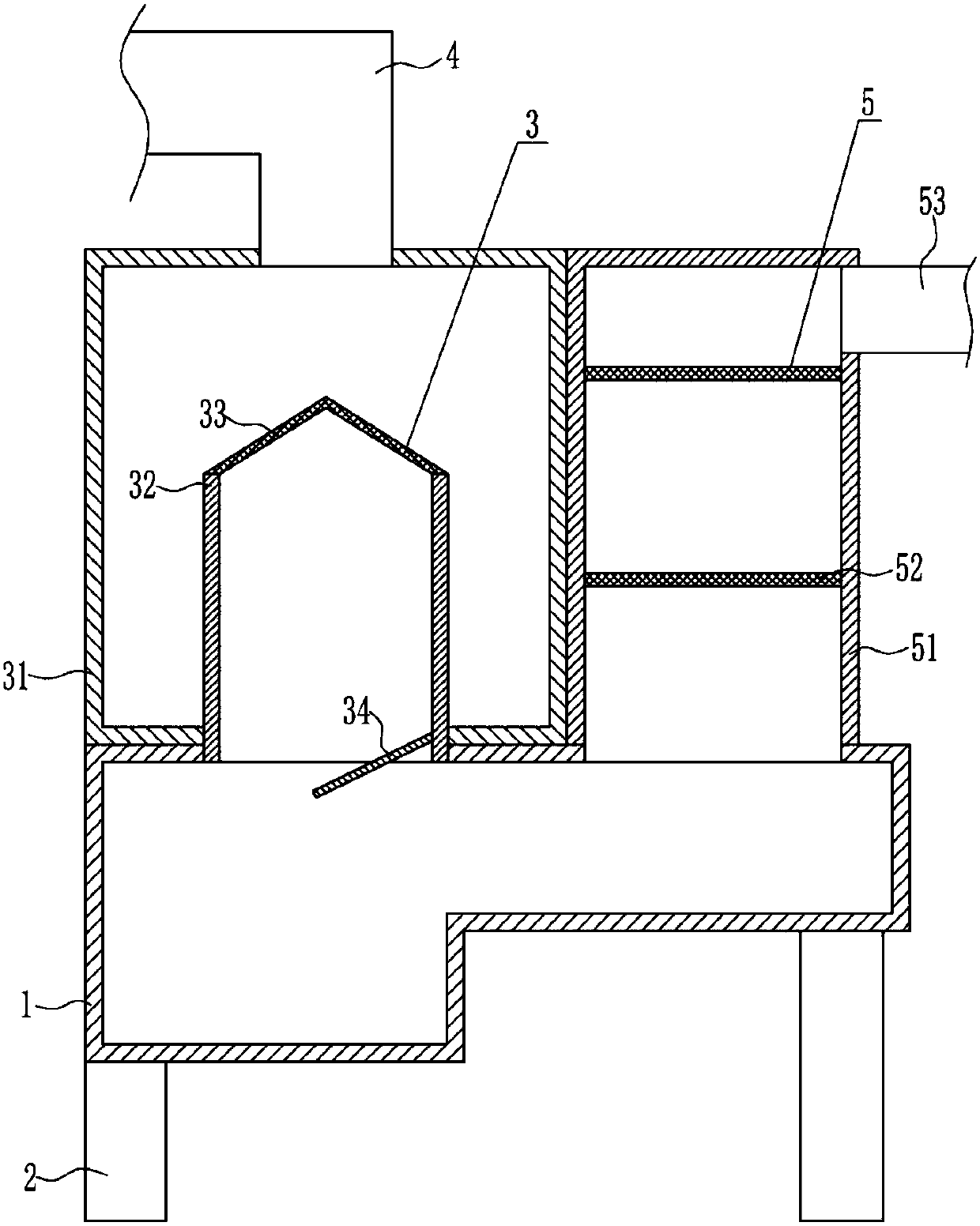
[0035] A sand filter device for petroleum exploitation, such as Figure 1-4 As shown, it includes a settling box 1, legs 2, a coarse filter 3, a feed pipe 4 and a fine filter 5, and the four corners of the bottom of the settling box 1 are equipped with a settling leg 2 by means of bolt connections, and the settling box 1 A coarse filter device 3 is provided on the left side of the top of the tank, a feed pipe 4 is provided on the top of the coarse filter device 3, and a fine filter device 5 is provided on the right side of the top of the sedimentation tank 1.

Embodiment 2

[0037] A sand filter device for petroleum exploitation, such as Figure 1-4 As shown, it includes a settling box 1, legs 2, a coarse filter 3, a feed pipe 4 and a fine filter 5, and the four corners of the bottom of the settling box 1 are equipped with a settling leg 2 by means of bolt connections, and the settling box 1 A coarse filter device 3 is provided on the left side of the top of the tank, a feed pipe 4 is provided on the top of the coarse filter device 3, and a fine filter device 5 is provided on the right side of the top of the sedimentation tank 1.

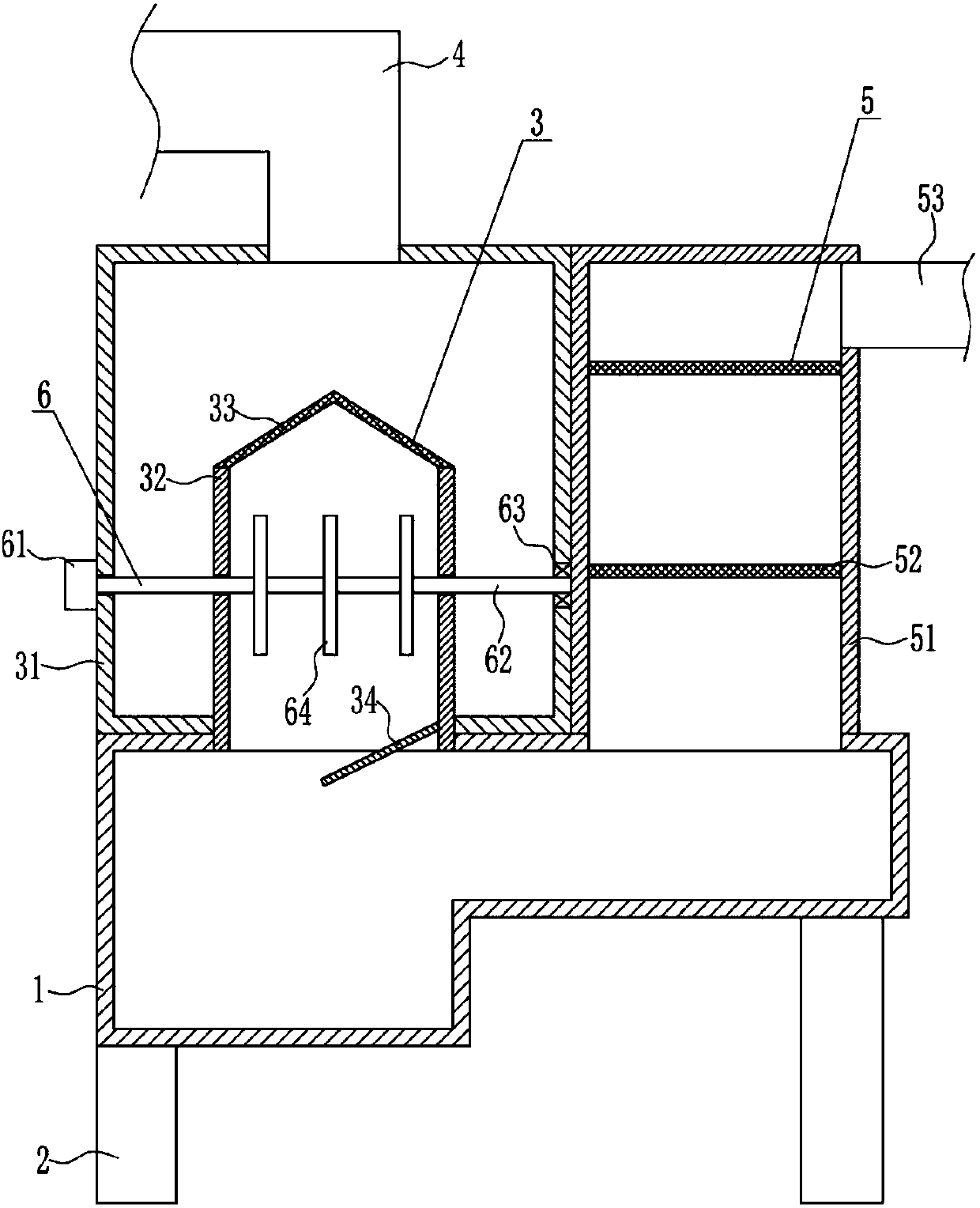
[0038] The coarse filtration device 3 includes a first box body 31, a frame body 32, a conical filter screen 33 and a slant plate 34. The left side of the top of the sedimentation tank 1 is connected with the first box body 31 by a bolt connection mode, and the feed pipe 4 It is connected to the middle of the top of the first box body 31 by means of bolt connection, the feed pipe 4 communicates with the first box body 3...

Embodiment 3

[0040] A sand filter device for petroleum exploitation, such as Figure 1-4 As shown, it includes a settling box 1, legs 2, a coarse filter 3, a feed pipe 4 and a fine filter 5, and the four corners of the bottom of the settling box 1 are equipped with a settling leg 2 by means of bolt connections, and the settling box 1 A coarse filter device 3 is provided on the left side of the top of the tank, a feed pipe 4 is provided on the top of the coarse filter device 3, and a fine filter device 5 is provided on the right side of the top of the sedimentation tank 1.

[0041] The coarse filtration device 3 includes a first box body 31, a frame body 32, a conical filter screen 33 and a slant plate 34. The left side of the top of the sedimentation tank 1 is connected with the first box body 31 by a bolt connection mode, and the feed pipe 4 It is connected to the middle of the top of the first box body 31 by means of bolt connection, the feed pipe 4 communicates with the first box body 3...


PUM


Abstract

The invention relates to a filtering device, in particular to a sand and stone filtering device for oil production. The technical problem to be solved by the invention is to provide a sand and stone filtering device for oil production, which is high in filtering efficiency, and clean and thorough in filtration. In order to solve the technical problem, the sand and stone filtering device for oil production, provided by the invention, comprises a settling tank and the like; supporting legs are mounted at four corners at the bottom of the settling tank in a manner of bolt connection; a coarse filtering device is arranged on the left side at the top of the settling tank; a feed pipe is arranged at the top of the coarse filtering device; a fine filtering device is arranged on the right side atthe top of the settling tank. The sand and stone filtering device for oil production, provided by the invention, has the benefits that through the coarse filtering device, the settling tank and the fine filtering device, sand and stones carried by oil are filtered and settled; through a stirring device and an accelerating device, the filtering efficiency is improved; through a material scraping device, the settled sand and stones are concentrated to the left part inside the settling tank, so that the effects of high filtering efficiency, and clean and thorough filtration are achieved.

Description

technical field [0001] The invention relates to a filter device, in particular to a sand filter device for petroleum exploitation. Background technique [0002] Petroleum, one of the main objects of geological exploration, is a viscous, dark brown liquid known as the "blood of industry." There are oil reserves in parts of the upper crust. The main component is a mixture of various alkanes, naphthenes and aromatic hydrocarbons. [0003] Oil extraction refers to the act of digging and extracting oil in places where oil is stored. In the process of oil extraction, oil and gas flow from the reservoir to the bottom of the well, and then rise from the bottom of the well to the wellhead. [0004] The sand and gravel are carried after the oil has just been mined, and the sand and gravel need to be filtered when the oil is processed. The current oil sand and gravel filtration equipment has low filtration efficiency, is not clean, and is not thorough. Therefore, it is urgent to dev...

Claims


Application Information

Patent Timeline
Patent Type & Authority Applications(China)
IPC IPC(8): B01D36/04C10G53/02
CPCB01D36/04C10G53/02
Inventor 魏文福周丛然劳国豪
Owner 魏文福
Why Eureka
Try Eureka