
Mechanical dismantling equipment for bridge pile foundation concrete spouting protection plate

A technology for concrete and protective panels, applied in sheet pile walls, infrastructure engineering, construction, etc., can solve the problems of high labor intensity, low work efficiency, and hidden safety hazards in protective panels, and achieves reduced labor intensity, simple operation, and improved performance. The effect of efficiency

Inactive Publication Date: 2018-02-27
汪成立
View PDF0 Cites 4 Cited by
  • Summary
  • Abstract
  • Description
  • Claims
  • Application Information

AI Technical Summary

Problems solved by technology

[0003] In order to solve the above problems, the present invention provides a mechanized removal equipment for bridge pile foundation concrete pouring protection boards, which can solve the existing need to manually use electric chisels to separate the protection boards from the solidified Concrete separation requires manual assistance in the process of removing the protective plate. The existing climbing tools are needed to remove the protective plate at a higher position. The splashed concrete particles in the process of manual use of electric chisels are easy to hurt the staff. , there are safety hazards in removing the protection board with the help of climbing tools, and the manual removal of the pile foundation concrete pouring protection board is complicated, labor-intensive and low in work efficiency. The function of mechanized removal of the pile foundation concrete pouring protection board can be realized without manual removal of the pile foundation The concrete pouring protective plate has no potential safety hazards, and has the advantages of simple operation, good safety, high stability, low labor intensity and high work efficiency.

Method used


Image

  • Mechanical dismantling equipment for bridge pile foundation concrete spouting protection plate
  • Mechanical dismantling equipment for bridge pile foundation concrete spouting protection plate
  • Mechanical dismantling equipment for bridge pile foundation concrete spouting protection plate

Examples


Embodiment Construction

[0025] In order to make the technical means, creative features, goals and effects achieved by the present invention easy to understand, the present invention will be further described below in conjunction with specific illustrations.

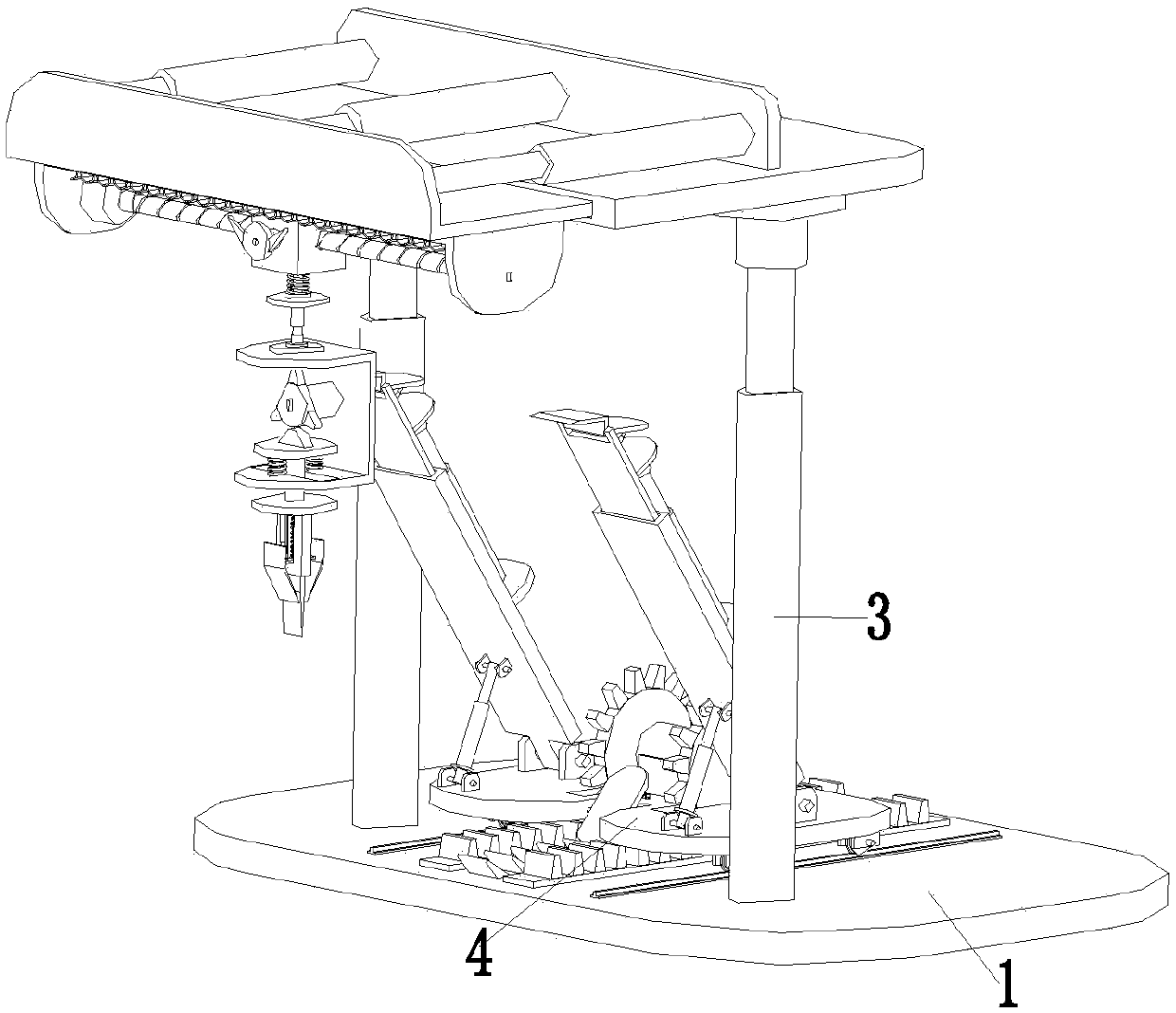
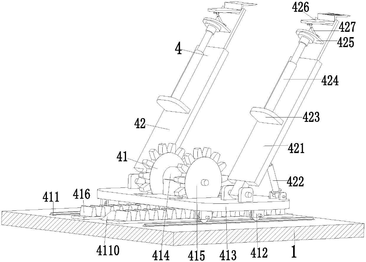
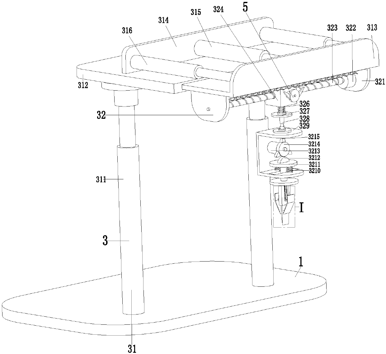
[0026] Such as Figure 1 to Figure 6 As shown, a mechanized demolition equipment for the concrete pouring protective plate of bridge pile foundation includes a bottom plate 1, and a reciprocating excavation device 3 is installed on the front side of the upper end of the bottom plate 1, and the reciprocating excavation device 3 can separate the protective plate to be removed from the solidified concrete Open, the base plate 1 is equipped with an auxiliary device 4, the auxiliary device 4 can assist the reciprocating excavation device 3 to work quickly and effectively, and the reciprocating excavation device 3 and the auxiliary device 4 cooperate with each other to complete the mechanized demolition process of the pile foundation concrete pouring p...


PUM


Abstract

The invention relates to a mechanized demolition device for concrete pouring protective plates of bridge pile foundations, which comprises a bottom plate, a reciprocating excavation device is installed on the front side of the upper end of the bottom plate, and an auxiliary device is installed on the bottom plate. The present invention can solve the problem of manual use of an electric chisel to separate the protective plate from the solidified concrete in the removal process of the existing pile foundation concrete pouring protective plate, and manual assistance is required in the process of removing the protective plate. Existing climbing tools are needed for demolition. Concrete particles splashed during manual work with electric chisels can easily injure the staff. Removing the protective plate with the help of climbing tools has potential safety hazards. The manual removal of the pile foundation concrete pouring protective plate is complicated. , High labor intensity and low work efficiency, can realize the function of mechanized demolition of the pile foundation concrete pouring protective plate.

Description

technical field [0001] The invention relates to the technical field of bridge pile foundation processing, in particular to a mechanized demolition device for concrete pouring protective plates of bridge pile foundations. Background technique [0002] The pile foundation is composed of a pile and a cap connected to the top of the pile. If the pile body is completely buried in the soil and the bottom of the cap is in contact with the soil, it is called a low cap pile foundation; if the upper part of the pile body is exposed to the ground and the bottom of the cap is above the ground, it is called a high cap pile foundation. Construction pile foundations are usually low cap pile foundations. Widely used in high-rise buildings, bridges, high-speed rail and other projects, among which bridge pile foundations are the most widely used. To build pile foundations, it is necessary to drill holes at the construction site, and then install the steel reinforcement cages bundled with pil...

Claims


Application Information

Patent Timeline
IPC IPC(8): E02D5/34
CPCE02D5/34
Inventor 汪成立
Owner 汪成立
Learn More