A Method for Determining Pressure in Sensing Chamber of Aircraft Hydraulic Brake Valve

A technology of aircraft hydraulic pressure and hydraulic braking, which is applied in the field of determining the pressure of the pressure sensing chamber of the hydraulic brake valve. It can solve the problems of inability to calculate the dynamic force of the pressure sensing chamber of the aircraft brake valve, the inability to optimize and improve the pilot's brake control experience, etc., to achieve optimization. The effect of improving the control feeling and improving the control quality

Active Publication Date: 2020-03-24
XIAN AVIATION BRAKE TECH
View PDF4 Cites 0 Cited by
  • Summary
  • Abstract
  • Description
  • Claims
  • Application Information

AI Technical Summary

Problems solved by technology

[0008] In order to overcome the working stroke generated by the pilot's actual manipulation of the aircraft brake valve in the prior art, the dynamic force calculation of the pressure in the pressure chamber of the aircraft brake valve cannot be carried out, so that the dynamic research on the control force characteristics of the hydraulic brake valve cannot be carried out. To optimize and improve the control experience of the pilot when braking, the present invention proposes a method for determining the pressure in the sensing pressure chamber of the hydraulic brake valve of the aircraft

Method used


Image

  • A Method for Determining Pressure in Sensing Chamber of Aircraft Hydraulic Brake Valve
  • A Method for Determining Pressure in Sensing Chamber of Aircraft Hydraulic Brake Valve
  • A Method for Determining Pressure in Sensing Chamber of Aircraft Hydraulic Brake Valve

Examples


Embodiment Construction

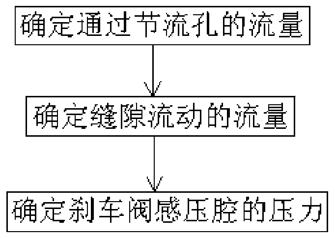
[0049] This embodiment is based on dynamic variables such as the brake pressure output by the brake nozzle of the hydraulic brake valve and the displacement of the spool to determine the pressure of the pressure chamber of the hydraulic brake valve of the aircraft. The specific process is:

[0050] Step 1, determine the flow rate q through the orifice 1 .

[0051] The flow rate q through the orifice 1 is the flow rate injected into the brake nozzle by the pressure sensing chamber through the orifice connected to the brake nozzle

[0052] The orifice connecting the pressure-sensing chamber and the brake nozzle is usually relatively small, and the flow through the orifice is determined by the small-hole throttling formula (1):

[0053]

[0054] where: q 1 is the flow through the orifice, in m 3 / s;

[0055] P g is the pressure in the pressure sensing chamber of the hydraulic brake valve, in MPa;

[0056] P b is the brake pressure output by the brake nozzle of the hydr...


PUM


Abstract

Disclosed is a method for determining the pressure of a plane hydraulic brake valve pressure sensing cavity. Through detailed stress analysis of a hydraulic brake valve element and detailed dynamic analysis of the braking controlling process, the specific and feasible pressure sensing cavity pressure determining method is provided from the dynamic changing rules of the pressure of the pressure sensing cavity in the processes of gradual building, maintaining and releasing of braking pressure, the change conditions of the controlling force of a hydraulic brake valve are mastered, control characteristic design of a braking system is conducted on the basis, the controlling feeling of a pilot during braking is optimized, and the controlling quality of the plane braking system is improved. The control characteristic design of the braking system is conducted based on the method, the controlling feeling of the pilot during braking is optimized, and the controlling quality of the plane brakingsystem is improved.

Description

technical field [0001] The invention relates to the field of wheel brake system control, in particular to a method for determining the pressure of a hydraulic brake valve sensing pressure chamber, which is used for studying the internal structural mechanical properties of the hydraulic brake valve. Background technique [0002] As an accessory product of the aircraft braking system, the hydraulic brake valve must be manipulated by the pilot to adjust the braking pressure acting on the wheels during take-off and landing taxiing. If the brake system also has anti-skid control function, the hydraulic brake valve can also be used. It functions to limit the maximum brake pressure acting on the wheels. [0003] A typical hydraulic brake valve structure is as follows: figure 1 As shown, it mainly consists of sleeve assembly 1, adjusting gasket 2, decompression spring assembly 3, valve core 4, guide sleeve 5, return spring 6, housing 7, valve sleeve 8, sealing ring 9, retaining rin...

Claims


Application Information

Patent Timeline
Patent Type & Authority Patents(China)
IPC IPC(8): F15B13/02
CPCF15B13/021F15B2211/50
Inventor 张谦张颖姝
Owner XIAN AVIATION BRAKE TECH
Why Eureka
Try Eureka