
A split adjustment frame for optical lens

An optical lens, split-type technology, applied in optics, optical components, instruments, etc., can solve the problem of insufficient installation space for common aperture optical lenses, and achieve the effect of solving the problem of insufficient installation space, easy assembly and compact structure

Active Publication Date: 2020-07-03
HEBEI HANGUANG HEAVY IND
View PDF5 Cites 0 Cited by
  • Summary
  • Abstract
  • Description
  • Claims
  • Application Information

AI Technical Summary

Problems solved by technology

[0003] In view of this, the purpose of the present invention is to provide a split adjustment frame for optical lenses, which can solve the problem of insufficient installation space for infrared imaging / semi-active laser co-aperture optical lenses

Method used


Image

  • A split adjustment frame for optical lens
  • A split adjustment frame for optical lens
  • A split adjustment frame for optical lens

Examples


Embodiment Construction

[0019] The present invention will be described in detail below with reference to the accompanying drawings and examples.

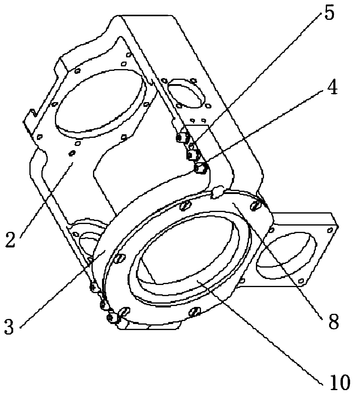
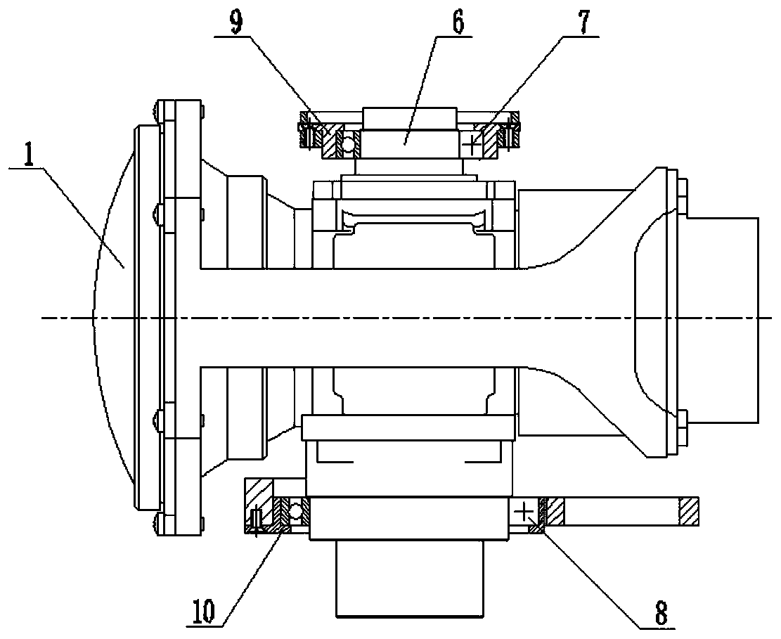
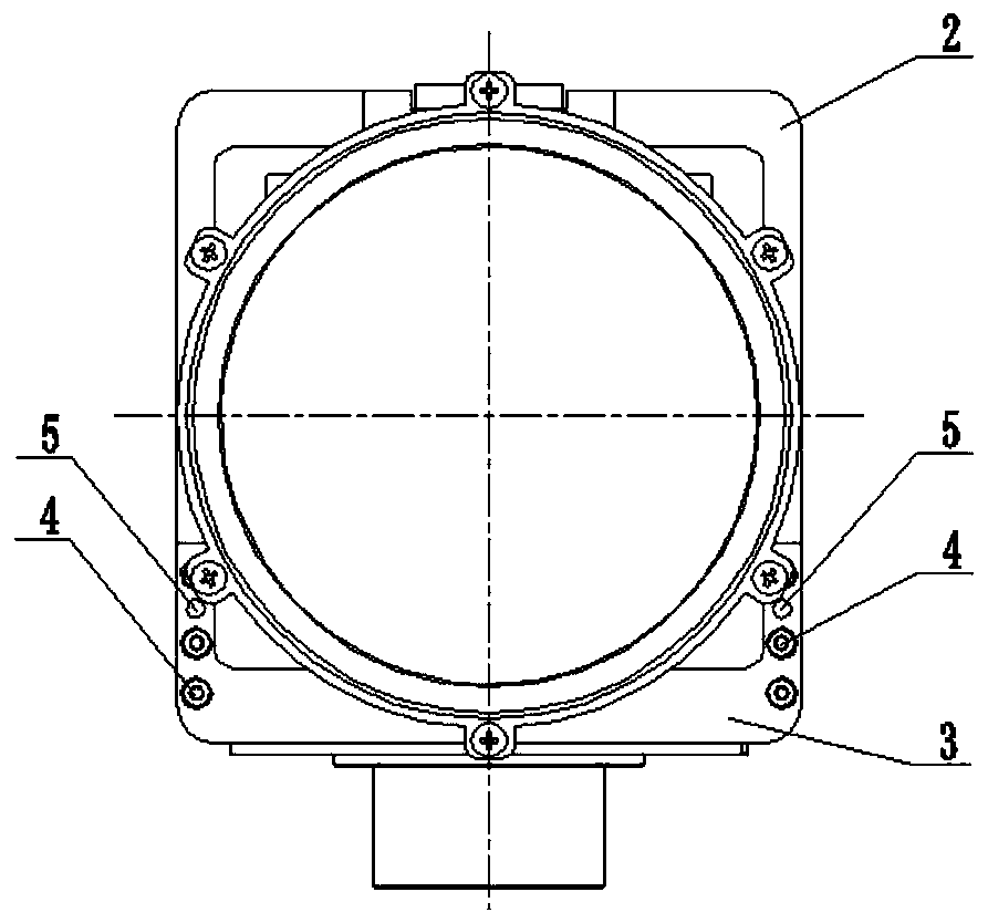
[0020] This embodiment provides a split adjustment frame for optical lenses, see attached figure 1 and 2 , comprising: a first frame 2, a second frame 3, a connecting screw 4, a positioning pin 5, an upper shaft 6, a first bearing 7, a second bearing 8, an upper bearing seat 9 and a lower bearing seat 10;

[0021] The part to be matched and installed is a co-aperture optical lens 1;

[0022] The first frame 2 is a U-shaped frame, and its three surfaces are respectively processed with through holes, wherein a rotating shaft connected with the co-aperture optical lens 1 is installed in the through holes on the opposite two sides;

[0023] The second frame 3 is an arc-shaped frame, and the end surfaces at both ends of the frame respectively extend two connecting blocks docked with the first frame 2;

[0024] The overall connection relationship is as follow...


PUM


Abstract

The invention discloses a split adjustment frame for an optical lens, which belongs to the technical field of the platform frame of the seeker optical cabin, and includes: a first frame, a second frame, an upper shaft, a first bearing, a second bearing, an upper Bearing seat and lower bearing seat; the first frame is a U-shaped frame; the second frame is an arc-shaped frame, and its two ends are provided with connecting blocks docked with the first frame; the co-caliber optical lens is installed on the first frame Inside, and the axis of the co-aperture optical lens is perpendicular to the axis of the through hole on the bottom surface of the first frame. The bearing and the upper bearing seat are installed on the first frame; the second frame is coaxially installed at the opening of the U-shaped first frame, and the connecting blocks of the second frame are respectively connected with the sides of the first frame to form a rectangular frame; the frame It can solve the problem of insufficient installation space of the infrared imaging / semi-active laser co-aperture optical lens.

Description

technical field [0001] The invention belongs to the technical field of a platform frame of an optical cabin of a seeker, and in particular relates to a split adjustment frame for an optical lens. Background technique [0002] With the rapid development of science and technology, the future war environment will become more and more complex, and the offensive and defensive confrontation will become more and more fierce. The strike capability of precision guided weapons will be seriously affected. In particular, single-mode guided weapons will be difficult to adapt to future wars. requirements. Therefore, the new generation of guided weapons will adopt multi-mode composite guidance, in which infrared imaging / semi-active laser common-aperture guidance technology is an important branch in this field, and because the lower part of the existing infrared imaging / semi-active laser common-aperture optical lens There is a semi-active laser optical system, which causes the entire lens ...

Claims


Application Information

Patent Timeline
Patent Type & Authority Patents(China)
IPC IPC(8): G02B7/02
CPCG02B7/022G02B7/023
Inventor 程大林周立媛蔡鹏张振华
Owner HEBEI HANGUANG HEAVY IND
Learn More