Machining Center Mechanism

A machining center and machine body technology, applied in the field of mechanical parts processing, can solve problems such as the detachment of the end of the spindle head, the reduction of the safety of the machining center mechanism, and the collision of the spindle head with the worktable or base, so as to avoid collision damage and improve the use of safety effect

Active Publication Date: 2019-01-04
FUXIN LIDA STEEL CASTING
View PDF11 Cites 0 Cited by
  • Summary
  • Abstract
  • Description
  • Claims
  • Application Information

AI Technical Summary

Problems solved by technology

[0003] During the downward movement of the spindle head, if no parts to be processed are placed on the workbench, the staff controls the downward movement of the spindle head. If the spindle head moves to the bottom of the spindle head guide rail, the staff has not stopped the downward movement of the spindle head. The end of the spindle head may break away from the guide rail of the spindle head, and the spindle head may collide with the worktable or base, which reduces the safety of the machining center mechanism

Method used


Image

  • Machining Center Mechanism
  • Machining Center Mechanism
  • Machining Center Mechanism

Examples


Embodiment Construction

[0037] The core of the present invention is to provide a machining center mechanism whose use safety is improved.

[0038] In order to enable those skilled in the art to better understand the technical solutions of the present invention, the present invention will be further described in detail below in conjunction with the accompanying drawings and embodiments.

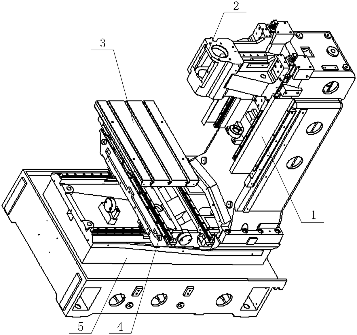
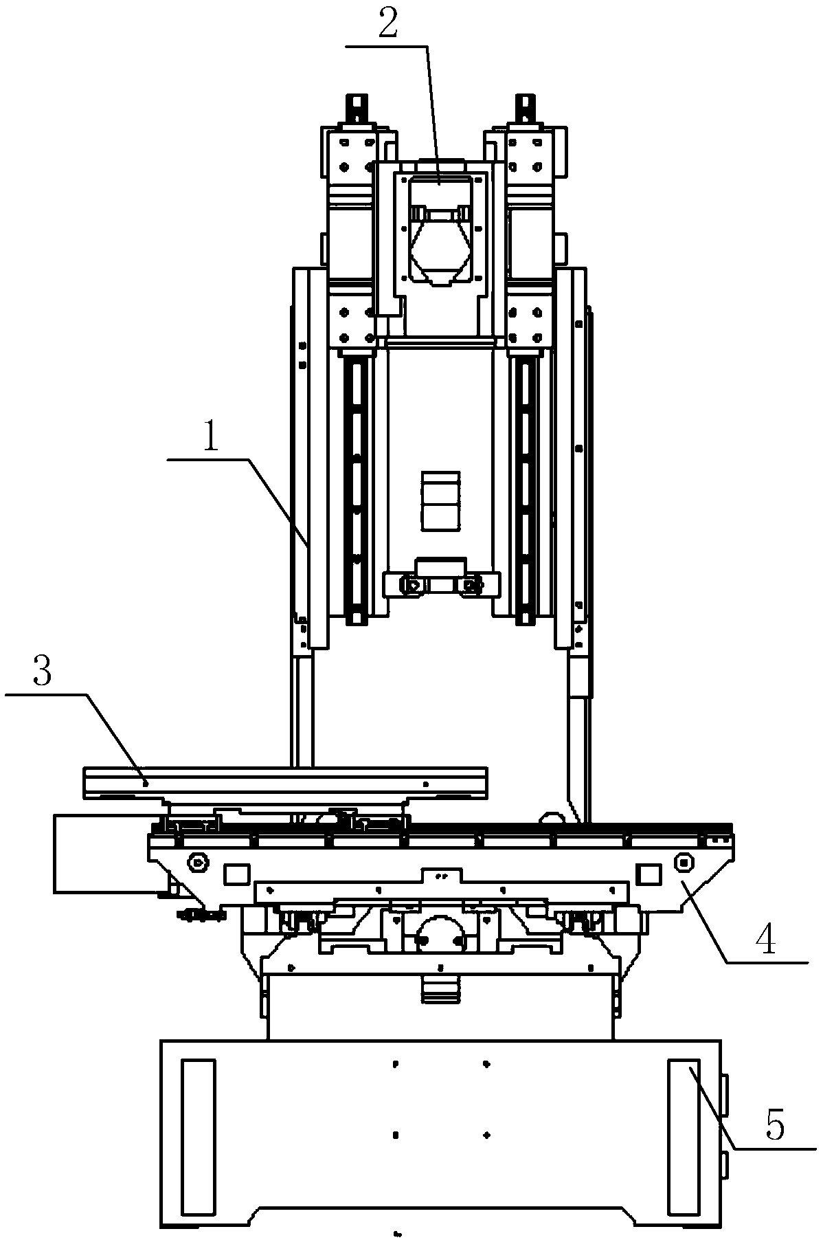
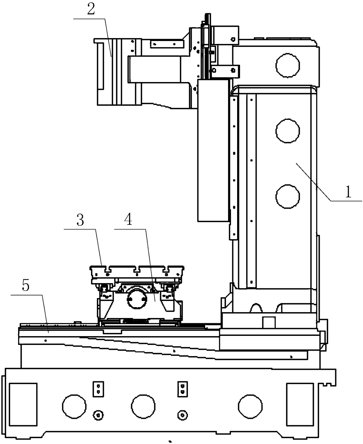
[0039] Please refer to Figure 1 to Figure 13 , in a specific embodiment, the machining center mechanism provided by the specific embodiment of the present invention includes a base 5, a column 1 and a spindle head 2 that is installed on the column 1 and can slide up and down along the column 1, and the column 1 is installed on the base 5 Above, the column 1 includes the column body 11, the shaft head guide rail 12, the shaft head anti-collision table 13 and the shaft head limit switch connected with the shaft head anti-collision table 13 and used to control the spindle head 2 to stop moving downward, two The spindl...


PUM


Abstract

The invention discloses a machining center mechanism. The machining center mechanism comprises a base, a stand column, and a main shaft head mounted on the stand column and capable of sliding up and down along the stand column; the stand column is mounted on the base; the stand column comprises a stand column body, shaft head guide rails, a shaft head collision preventing table, and a shaft head limiting switch connected with the shaft head collision preventing table and used for controlling the main shaft head to stop downwards moving; two shaft head guide rails are arranged on the stand column body, and are arranged in parallel; the shaft head collision preventing table is arranged on the stand column body, and is positioned between the two shaft head guide rails; and the shaft head collision preventing table can butt against the bottom end of the main shaft head. As the machining center mechanism is provided with the shaft head collision preventing table and the shaft head limitingswitch connected with the shaft head collision preventing table, when the main shaft head moves to a limit position at the bottom end, the main shaft head is stopped from downwards moving through theshaft head limiting switch by touching the shaft head collision preventing table, the collision damage condition of the main shaft head is prevented, and the use safety of the machining center mechanism is effectively improved.

Description

technical field [0001] The invention relates to the technical field of machining of mechanical parts, in particular to a machining center mechanism. Background technique [0002] The machining center mechanism includes a base, a saddle, a worktable, a column and a spindle head that can be raised and lowered along the column. The saddle and column are installed on the base, and the workbench is installed on the saddle. The spindle head is used as the spindle system of the machining center. The cantilever The beam form is suspended on one side of the column and must bear a large bending moment. The column includes a column body and a shaft head guide rail. Specifically, the spindle head is slidably connected to the shaft head guide rail, and slides up and down along the shaft head guide rail. [0003] During the downward movement of the spindle head, if no parts to be processed are placed on the workbench, the staff controls the downward movement of the spindle head. If the s...

Claims


Application Information

Patent Timeline
Patent Type & Authority Patents(China)
IPC IPC(8): B23Q11/00B23Q17/22
CPCB23Q11/00B23Q17/2208
Inventor 刘沙刁万红白旭东
Owner FUXIN LIDA STEEL CASTING
Why Eureka
Try Eureka