Electromagnet attraction detecting device

A detection device and electromagnet technology, which is applied in the field of electromagnet detection, can solve problems such as inaccurate values, easy to produce deviations, and inaccurate acquisition of electromagnet suction, and achieve the effect of saving time and omitting calculations

Pending Publication Date: 2018-03-02
SUZHOU LVKON TRANSMISSION TECH CO LTD
View PDF10 Cites 7 Cited by
  • Summary
  • Abstract
  • Description
  • Claims
  • Application Information

AI Technical Summary

Problems solved by technology

[0002] The value of the suction force of the existing electromagnet needs to be obtained through complex calculations. Due to the complexity of the calculation process and the fact that the electromagnet itself will deviate from the design during production, the value obtained through complex calculations may not be accurate; In the actual production process, factors such as the ampere-turn value, the polarization area of ​​the iron core, the air gap value of the armature and the armature core will affect the suction force of the electromagnet, among which the ampere-turn value and the polarization area of ​​the armature are the characteristics of the part itself and are not easy to change. , and the air gap value of the armature and the armature core is relatively more likely to deviate, which makes it impossible to accurately obtain the suction force of the existing side electromagnet

Method used


Image

  • Electromagnet attraction detecting device
  • Electromagnet attraction detecting device
  • Electromagnet attraction detecting device

Examples


Embodiment Construction

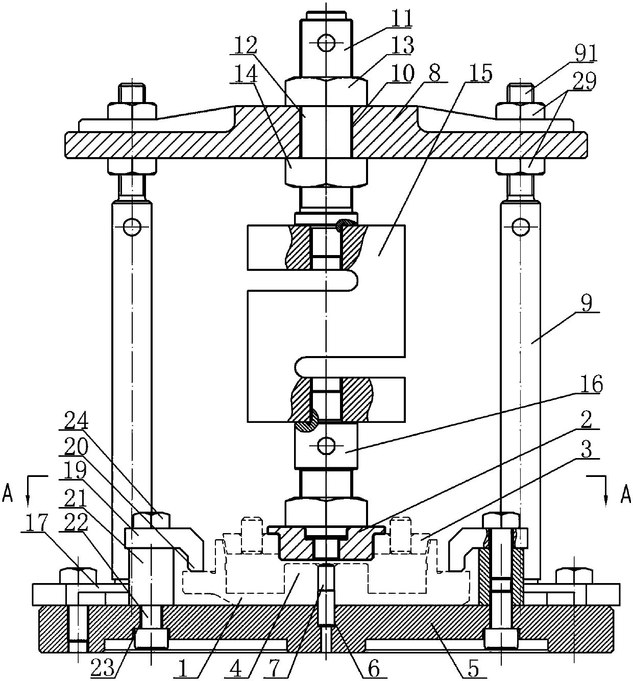
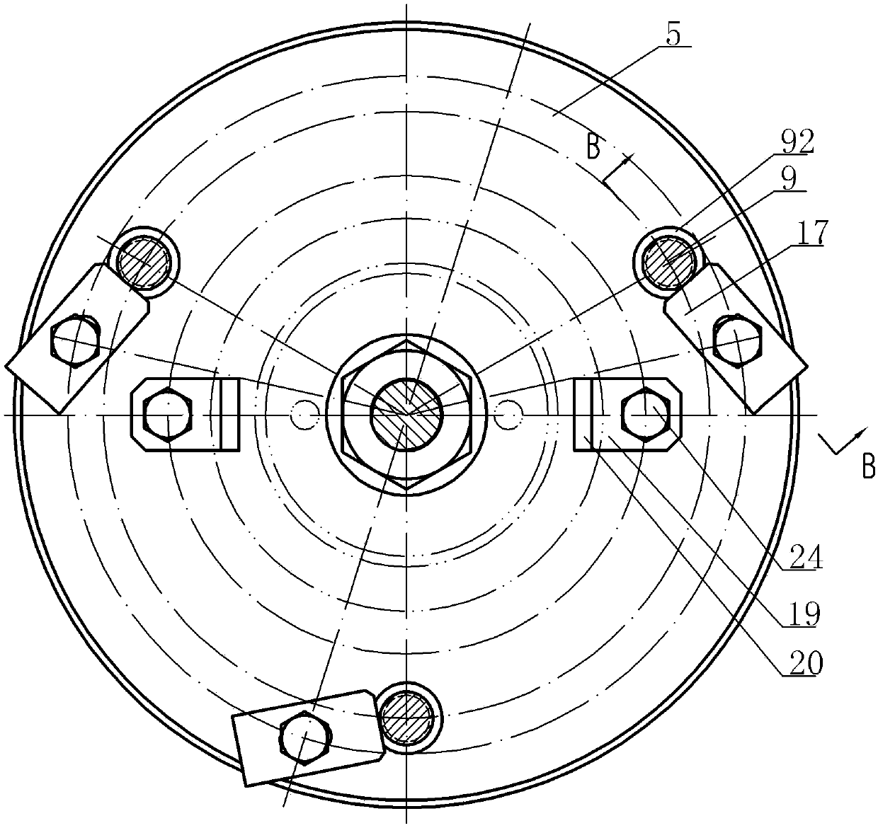
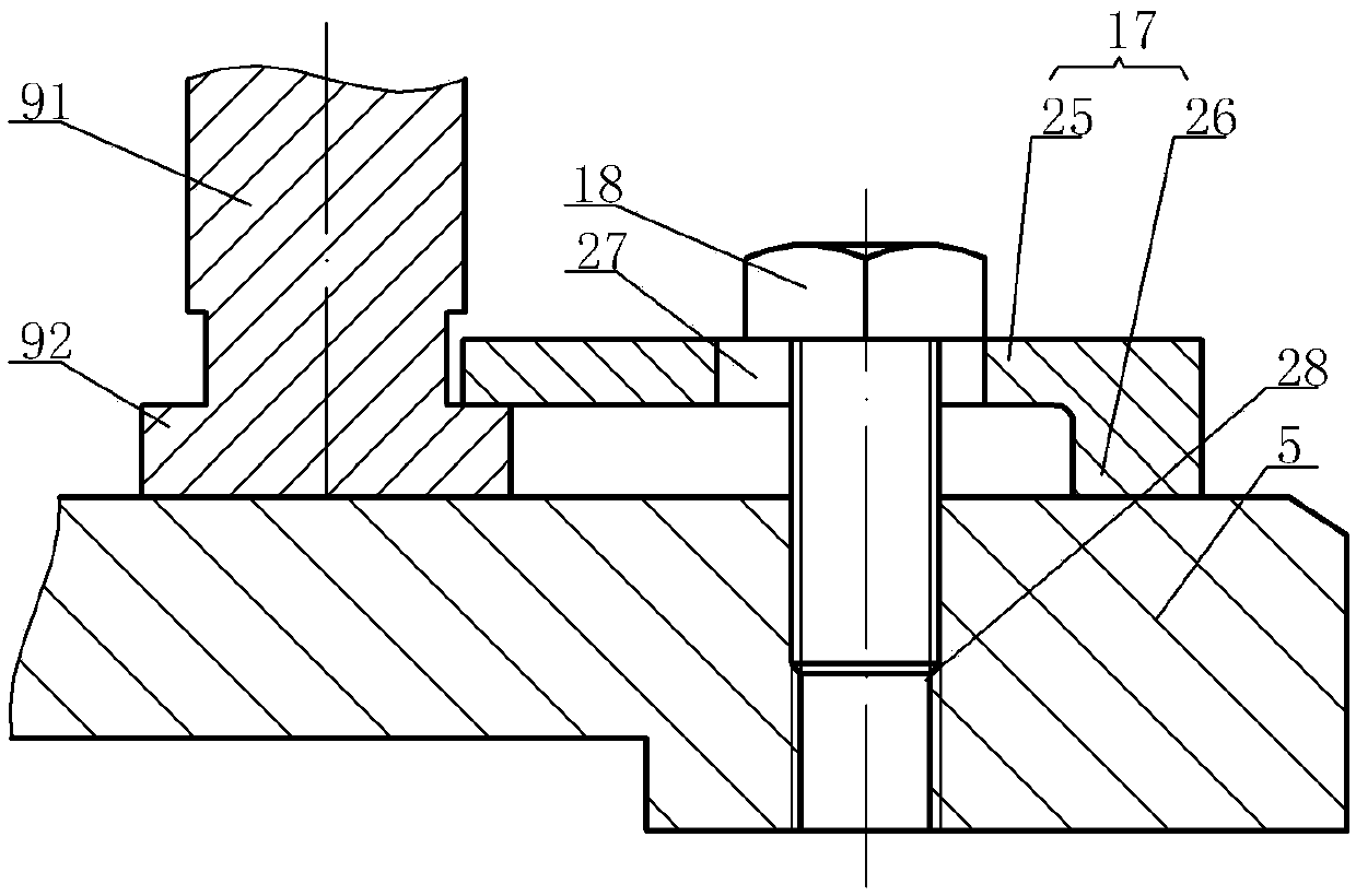
[0016] Electromagnet suction detection device, see Figure 1 ~ Figure 3 : The electromagnet to be tested includes a yoke 1, an armature 2, and a coil 3. The center of the yoke 1 is arranged with an upwardly convex armature core 4, which includes a base 5. The center of the base 5 is provided with a central positioning through hole 6. The center position of the trial yoke 1 is positioned and fixed in the center positioning through hole 6 through the step pin 7, and an upper plate 8 is arranged directly above the base 5, and the upper plate 8 is supported directly above the base 5 through several support rods 9, A vertical through hole 10 is provided directly above the upper plate 8 relative to the center positioning through hole 6, and the middle screw part 12 of the upper pull rod 11 penetrates the vertical through hole 10 and is fixed to the upper plate through the upper nut 13 and the lower nut 14. 8. The lower end of the upper pull rod 11 is affixed to the upper end of the ...


PUM


Abstract

The invention provides an electromagnet attraction detecting device capable of accurately obtaining an electromagnet attraction value by controlling an air gap value between an armature and an armature core so as to accurately display the electromagnet attraction, thereby eliminating laborious calculation and saving time. An electromagnet to be tested comprises a magnetic yoke, an armature and a coil. A convex armature core is arranged at the center of the magnetic yoke. The electromagnet attraction detecting device is characterized in that the electromagnet attraction detecting device comprises a base, a center positioning through hole is arranged in the center of the base; the central position of the magnetic yoke to be tested is fixedly installed in the center positioning through hole by a step pin; an upper plate is disposed right above the bas and is supported right above the base by a plurality of support rods; a vertical through hole is disposed right above the upper plate relative to the center positioning through hole; the middle screw portion of a upper pull rod passes through the vertical through hole and then is fixed to the upper plate by a upper nut and a lower nut; and the lower end of the upper pull rod is fixedly connected with the upper end of a tension sensor.

Description

technical field [0001] The invention relates to the technical field of electromagnet detection, in particular to an electromagnet suction detection device. Background technique [0002] The value of the suction force of the existing electromagnet needs to be obtained through complex calculations. Due to the complexity of the calculation process and the fact that the electromagnet itself will deviate from the design during production, the value obtained through complex calculations may not be accurate; In the actual production process, factors such as the ampere-turn value, the polarization area of ​​the iron core, the air gap value of the armature and the armature core will affect the suction force of the electromagnet, among which the ampere-turn value and the polarization area of ​​the armature are the characteristics of the part itself and are not easy to change. , and the air gap value of the armature and the armature core is relatively more likely to deviate, which make...

Claims


Application Information

Patent Timeline
Patent Type & Authority Applications(China)
IPC IPC(8): G01R33/12
CPCG01R33/12
Inventor 李磊杨海华陈家炜吴茂瑞
Owner SUZHOU LVKON TRANSMISSION TECH CO LTD
Why Eureka
Try Eureka