Reagent storage device

A technology for storage devices and reagents, applied in household refrigeration devices, packaging, transportation and packaging, etc., can solve the problems of high-pressure pipeline safety hazards, easily affecting experimental results, and low degree of automation, achieving a high degree of automation and facilitating later maintenance. , Compatible with a wide range of effects

Active Publication Date: 2018-06-01
MGI TECH CO LTD
View PDF7 Cites 5 Cited by
  • Summary
  • Abstract
  • Description
  • Claims
  • Application Information

AI Technical Summary

Problems solved by technology

Existing reagent storage devices generally use compression refrigeration technology or air-cooling technology for temperature control, and the vibration is serious during the working process, which is not only noisy, but also easily affects the experimental results; furthermore, t

Method used


Image

  • Reagent storage device
  • Reagent storage device
  • Reagent storage device

Examples


Embodiment 1

[0045] Embodiment 1 (the first reagent storage device):

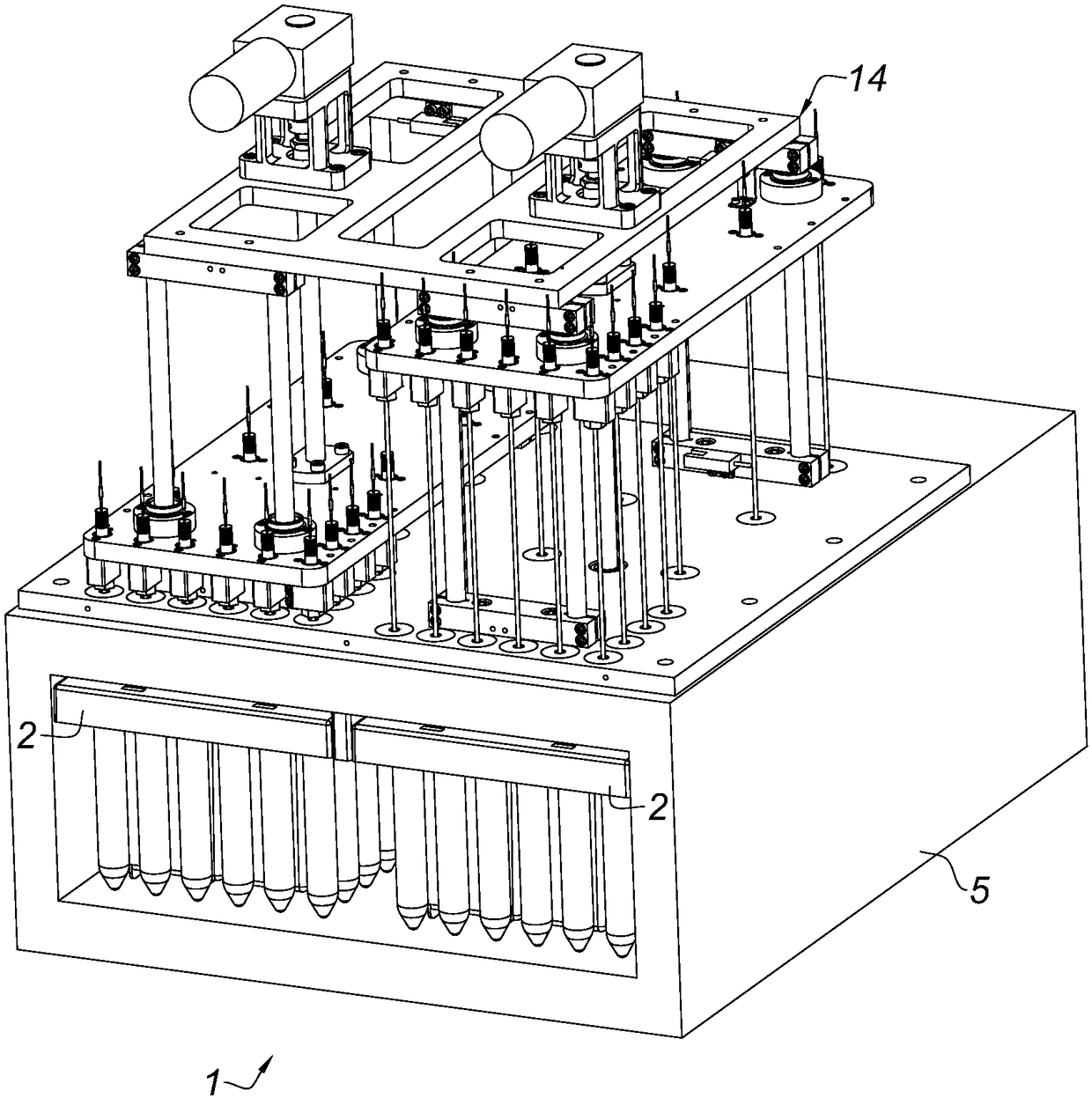
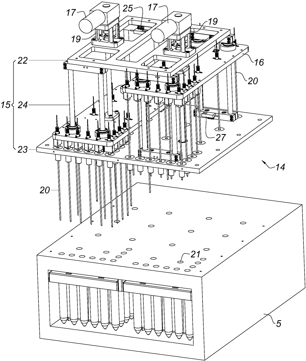
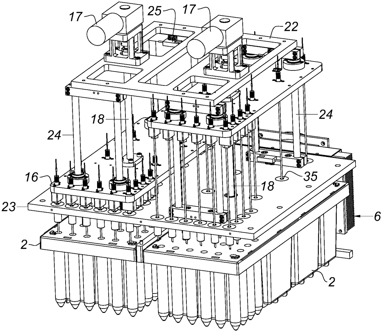
[0046] see Figure 1-Figure 11 , the present embodiment provides a reagent storage device 1, which includes:

[0047] Reagent box 2, it is provided with several reagent accommodating cavities 3, see specifically Figure 10 and Figure 11 , the reagent box 2 contains reagent chambers 3 of different shapes, which are mainly tubular and cuboid in the figure, and these reagent chambers 3 have an opening at the upper end; the upper surface 4 of the kit 2 is provided with a sealing film, The sealing film seals each reagent containing cavity, that is, the sealing film seals each opening, Figure 10 hides the seal;

[0048] Heat-insulating box 5, the wall of which is filled with heat-insulating and heat-preserving materials, the test kit 2 is placed in the heat-insulating box 5, and a temperature sensor is arranged in the heat-insulating box 5 for monitoring the temperature in the box;

[0049] The temperature control modu...

Embodiment 2

[0060] Embodiment 2 (the second reagent storage device):

[0061] see Figure 12-Figure 19 , the present embodiment provides a reagent storage device 1', which includes:

[0062] Reagent box 2', which is provided with several reagent accommodating cavities, the upper surface of the reagent box 2' is provided with a sealing film, and the sealing film seals each reagent accommodating cavity;

[0063] Insulated box 5' is provided with a door 36', and the test kit 2' is placed in the insulated box 5', which is provided with a temperature sensor in the insulated box 5';

[0064] The temperature control module 6' is located on the heat insulation box 5', and the temperature control module 6' includes built-in heat transfer fins, external heat transfer fins, Peltier refrigeration heaters, heat insulation cotton, built-in fans and External fan, heat insulation cotton is sandwiched between the built-in heat transfer fins and external heat transfer fins, the heat insulation cotton has...


PUM


Abstract

The invention belongs to the technical field of biochemical appliances, and provides two types of reagent storage device. A first type reagent storage device includes a reagent box, a thermal insulating box, a temperature control module, and a motion module; the reagent box has a seal film and is placed in the thermal insulating box; a temperature sensor is arranged in the thermal insulating box;a temperature control module is arranged on the thermal insulating box; the temperature control module adopts a Peltier effect principle to work; a motion module body is arranged outside the thermal insulating box; and the motion module can drive a reagent needle to puncture the seal film of the reagent box to suck a reagent. The second type of reagent storage device is similar to the first type of reagent storage device, and the main difference between the first type reagent storage device and the second type of reagent storage device is that a motion module of the second type reagent storagedevice is arranged in the thermal insulating box, and a door is arranged on the thermal insulating box. The reagent storage device is simple in structure, facilitates assembly and later maintenance,can be transplanted on different appliances, and is wide in compatible range; the temperature control module can avoid noise and vibration, is safe to use, can rapidly achieve cooling and heating, andis excellent in temperature control effect.

Description

technical field [0001] The invention belongs to the technical field of biochemical equipment, and in particular relates to a reagent storage device. Background technique [0002] Biochemical instruments and medical instruments, such as PCR instruments, blood sample analyzers, gene sequencers, etc., generally require the input of various reagent solutions for detection and experimental operations. There are many types of reagents, so they all have reagent storage devices. However, the existing reagent storage device has a complex structure, is not easy to assemble, and has poor compatibility with different instruments / instruments, which is not conducive to modular production, resulting in high manufacturing costs and is not conducive to later maintenance. [0003] Based on the current technical level, it takes hours or even days for the above-mentioned instruments / instruments to complete an experiment, therefore, the reagents need to be stored at a suitable temperature, other...

Claims


Application Information

Patent Timeline
IPC IPC(8): B65D81/38B65D81/18B65D25/02
CPCB65D25/02B65D81/18B65D81/3813
Inventor 张松振王景刘健谭大喜张文宇孙磊林文思成
Owner MGI TECH CO LTD
Why Eureka
Try Eureka