
Sand blasting nozzle

A technology of sandblasting nozzles and sand bins, which is applied in the direction of spray guns, explosion generating devices, abrasives, etc., can solve the problems of poor sandblasting effect, narrow distribution area, low efficiency, etc., achieve uniform surface treatment effect, uniform and stable spraying, The effect of increasing the spray area

Active Publication Date: 2018-03-06
CHONGQING YOUTE MOLD CO LTD
View PDF7 Cites 0 Cited by
  • Summary
  • Abstract
  • Description
  • Claims
  • Application Information

AI Technical Summary

Problems solved by technology

[0002] The sandblasting nozzle is the component that finally ejects the sand shot during shot blasting. The existing sandblasting nozzle is usually a cylindrical metal pipe body, and the sand outlet end of some round tubular sandblasting pipes is a pointed mouth. The structure is simple, and the sandblasting effect is not good. Because the sand shot has been transported and sprayed in the circular channel, and the flow state is stable, most of the sand shot is clustered in a straight line after spraying. When spraying, the center position is too concentrated, and the surrounding area is too scattered , the distribution surface is narrow, which is more suitable for sandblasting of hard and micro parts, but for general sandblasting treatment, the sandblasting surface is insufficient and the efficiency is low, especially some soft materials are easy to cause local excessive erosion

Method used


Image

  • Sand blasting nozzle

Examples


Embodiment Construction

[0015] The implementation of the present invention will be illustrated by specific specific examples below, and those skilled in the art can easily understand other advantages and effects of the present invention from the contents disclosed in this specification.

[0016] Below in conjunction with accompanying drawing and embodiment the present invention will be further described:

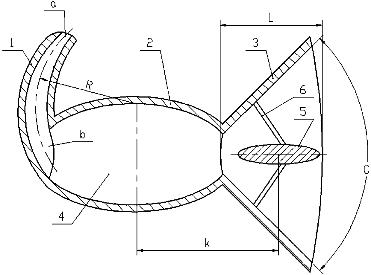
[0017] Such as figure 1 As shown, a sandblasting nozzle includes a feed pipe 1, a sand holding bin 2, and a spraying part 3. The sand holding bin 2 has an ellipsoidal cavity 4 and one end of the long axis of the cavity 4 has a The inlet, the feed pipe 1 is a circular arc pipe section, the outlet of the feed pipe 1 is connected to the inlet of the sand container 2 cavity, and the arc convex direction of the feed pipe 1 is as long as the cavity 4 The protruding ends in the axial direction have the same protruding direction, and an outlet is provided at the other end of the long axis of the cavity 4 ...


PUM


Abstract

The invention discloses a sand blasting nozzle. The sand blasting nozzle comprises a feed pipe, a sand accommodating bin and a spraying part; the sand accommodating bin is provided with an elliptically spherical cavity; an inlet is formed in one end of a long shaft of the cavity; the feed pipe is an arc pipe section; an outlet of the feed pipe is connected with the inlet of the cavity of the sandaccommodating bin; the arc projection direction of the feed pipe is consistent with the projection direction of a projection end in the long shaft direction of the cavity; an outlet is formed in the other end of the long shaft of the cavity; the spraying part is horn-shaped; a small end of the spraying part is connected with an outlet end of the cavity; the axis of the spraying part is coaxially arranged with the long shaft of the cavity; an elliptically spherical flow separation body with a long shaft coaxial with the long shaft of the cavity is arranged in a horn mouth of the spraying part;the flow separation body is fixed on multiple connecting ribs on the inner wall of the spraying part for support fixation; one ends of the connecting ribs are fixed on the inner wall of the spraying part, and the other ends are fixed on the surface of the flow separation body; and all the connecting ribs are circularly arranged with the axis of the spraying part as center. The sand blasting nozzlecan uniformly blast sand shots, and is larger in blasting area.

Description

technical field [0001] The invention belongs to the technical field of sandblasting, in particular to a sandblasting nozzle for sandblasting. Background technique [0002] The sandblasting nozzle is the component that finally ejects the sand shot during shot blasting. The existing sandblasting nozzle is usually a cylindrical metal pipe body. The structure is simple, and the sandblasting effect is not good. Since the sand shot has been transported and sprayed in the circular channel, and the flow state is stable, most of the sand shot is clustered and straight after spraying. When spraying, the center position is too concentrated, and the surrounding area is too scattered. , The distribution surface is narrow, which is more suitable for sandblasting of hard and micro parts, but for general sandblasting treatment, the sandblasting surface is insufficient and the efficiency is low, especially some soft materials are easy to cause local excessive erosion. Contents of the inven...

Claims


Application Information

Patent Timeline
Patent Type & Authority Applications(China)
IPC IPC(8): B24C5/04
CPCB24C5/04
Inventor 雷佳乐朱裕华
Owner CHONGQING YOUTE MOLD CO LTD
Learn More