A new type of anti-drop device for bridge construction

A bridge construction and anti-drop technology, which is applied in bridges, bridge construction, erection/assembly of bridges, etc., can solve the problems of short service life of anti-fall devices, small maximum bearing capacity of anti-fall devices, and poor anti-fall effects. Achieve the effect of preventing damage, prolonging service life and preventing deformation

Inactive Publication Date: 2019-05-14
GANSU ROAD & BRIDGE CONSTR GROUP
View PDF8 Cites 1 Cited by
  • Summary
  • Abstract
  • Description
  • Claims
  • Application Information

AI Technical Summary

Problems solved by technology

[0005] Aiming at the deficiencies in the prior art, the purpose of the present invention is to provide a novel bridge construction anti-fall device to solve the problem that the connection between the bridge construction anti-fall device and the bridge in the prior art is relatively weak, and the maximum size of the anti-fall device Defects of small bearable force, short service life of the anti-drop device, and poor anti-drop effect

Method used


Image

  • A new type of anti-drop device for bridge construction
  • A new type of anti-drop device for bridge construction
  • A new type of anti-drop device for bridge construction

Examples


Embodiment 1

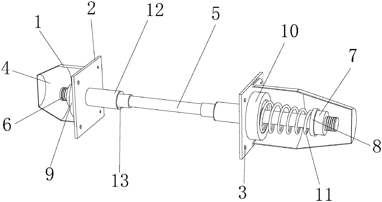
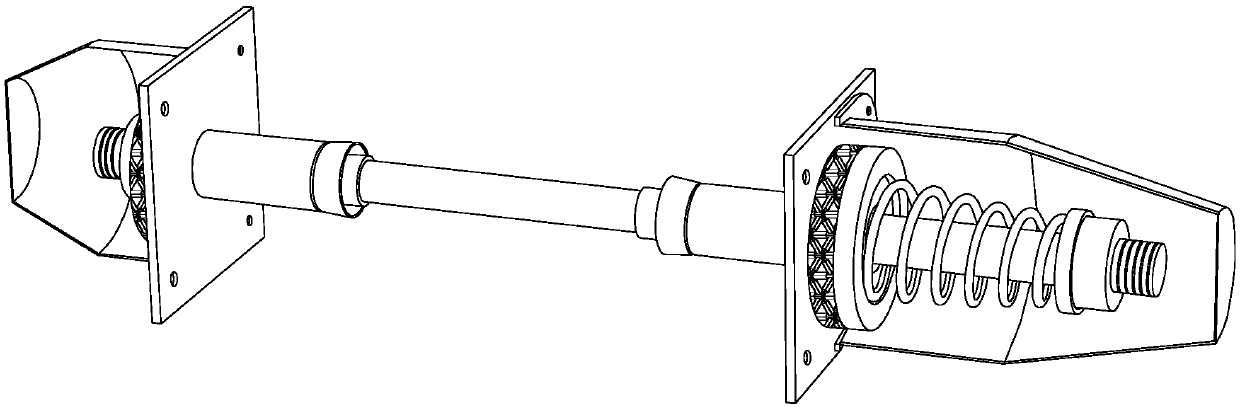
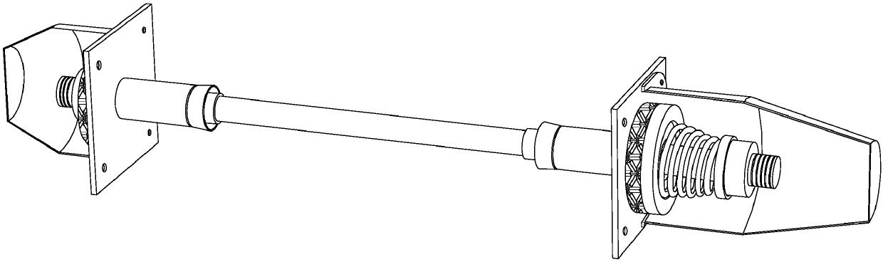
[0034] see Figure 1-Figure 7 , the present invention provides a new type of technical solution for bridge construction fall prevention device: its structure includes a protective shell cover 1, a stopper plate 2, a fixing screw hole 3, a telescoping limited cavity 4, a deformable sliding rod 5, a fixing thread 6, Set nut 7, welding gasket 8, starting welding ring 9, terminal welding ring 10, strong spring 11, fixed sleeve 12, telescopic movable joint 13, the protective shell cover 1 and the stop plate 2 are equipped with two , the protective cover 1 is respectively arranged on the outer surface of the stop plate 2, the port of the protective cover 1 is provided with a flange, and the stop plate 2 is rectangular and equidistantly provided with four fixing screw holes 3 , the fixing screw hole 3 and the baffle plate 2 are integrally formed, and the protective shell 1 is connected with the baffle plate 2 in a vertical or vertical shape through the cooperation of the flange plate...

Embodiment 2

[0038] see Figure 1-Figure 12 , the present invention provides a new type of technical solution for bridge construction fall prevention device: its structure includes a protective shell cover 1, a stopper plate 2, a fixing screw hole 3, a telescoping limited cavity 4, a deformable sliding rod 5, a fixing thread 6, Set nut 7, welding gasket 8, starting welding ring 9, terminal welding ring 10, strong spring 11, fixed sleeve 12, telescopic movable joint 13, the protective shell cover 1 and the stop plate 2 are equipped with two , the protective cover 1 is respectively arranged on the outer surface of the stop plate 2, the port of the protective cover 1 is provided with a flange, and the stop plate 2 is rectangular and equidistantly provided with four fixing screw holes 3 , the fixing screw hole 3 and the baffle plate 2 are integrally formed, and the protective shell 1 is connected with the baffle plate 2 in a vertical or vertical shape through the cooperation of the flange plat...


PUM


Abstract

The invention discloses a novel bridge construction anti-falling device which structurally comprises two protective shell covers, two baffles, fixing screw holes, a retractable limiting cavity, a deformable sliding rod, a fixing thread, a locking nut, a welding spacer, an initial end welding ring, a terminal welding ring, a strong spring, a fixing sleeve and an expansion and contraction movable joint. The protective shell covers are arranged on the outer side surfaces of the baffles correspondingly, and flange plates are arranged at an inner end openings of the protective shell covers; and thebaffles are evenly provided with the four fixing screw holes in a rectangular mode at equal intervals, and the fixing screw holes and the baffles are of an integrally-formed structure. The novel bridge construction anti-falling device has the beneficial effects that by enhancing the connecting firmness between the bridge construction anti-falling device and a bridge, the maximum bearable force ofthe device is increased, the bridge construction anti-falling device is protected, and the service life of the novel bridge construction anti-falling device is prolonged accordingly; and meanwhile, bridge collapse is effectively avoided, the bridge is protected, and thus the cost in the aspect of bridge maintenance is reduced.

Description

technical field [0001] The invention is a novel bridge construction fall prevention device, which belongs to the technical field of bridge construction equipment. Background technique [0002] Bridge construction refers to the process of building a bridge according to the design content; it mainly refers to bridge construction technology, construction organization, construction management, construction quality, etc. [0003] The prior art discloses application number CN201720121621.4, a bridge construction fall prevention device. The invention discloses an anti-drop device for bridge construction, which comprises a fixed frame body, a horizontal plate, a sliding rod, a fixed pin and a winch. A support base is welded on the fixed frame body, and a first foot is fixedly arranged inside the fixed frame body. Step on the pedal, a handrail bar is installed on the first foot pedal, the two ends of the horizontal plate are welded on the fixed frame, the upper and lower ends of the...

Claims


Application Information

Patent Timeline
Patent Type & Authority Patents(China)
IPC IPC(8): E01D21/00
CPCE01D21/00
Inventor 田过勤谢晓燕康谦蒋利亚
Owner GANSU ROAD & BRIDGE CONSTR GROUP
Why Eureka
Try Eureka