Changeable curved-surface stage
A stage and curved surface technology, applied in the field of multi-variable curved surface stage, can solve the problems of inability to adapt to the diversified needs of the performing arts market and the inability to change the plane structure, and achieve the effects of precise movements, good manufacturing process, and easy control.
- Summary
- Abstract
- Description
- Claims
- Application Information
AI Technical Summary
Problems solved by technology
Method used
Image

Examples
Embodiment Construction
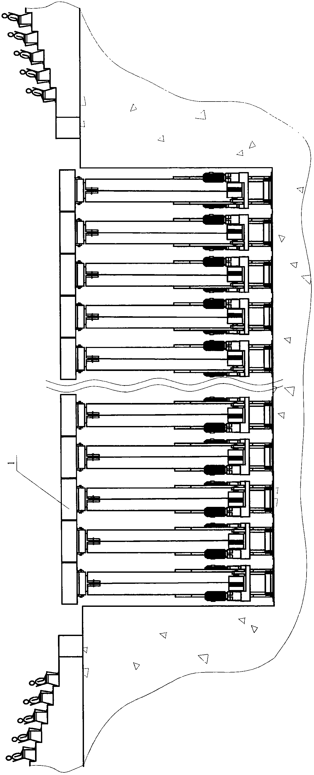
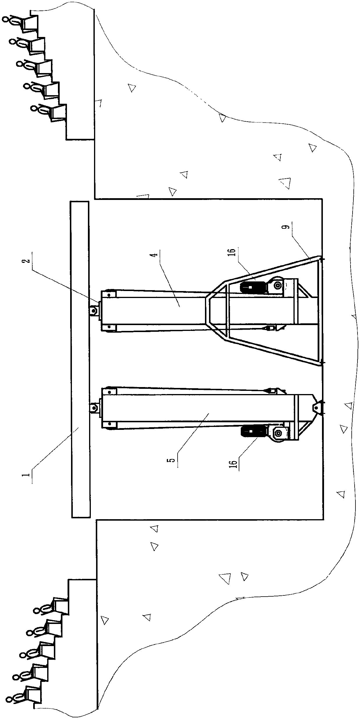
[0022] refer to Figure 1-10 , a stage with variable curved surface, which is composed of a plurality of mutually independent table top units, and the table top unit includes a table top 1 and an independent lifting adjustment device installed under the table top, and all the table tops in the initial state have gaps along the width arranged side by side;
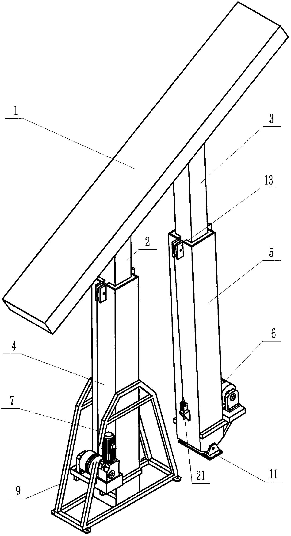
[0023] The lifting adjustment device includes a longitudinally arranged first sliding column 2, a longitudinally arranged second sliding column 3, a fixed sliding sleeve 4, a swinging sliding sleeve 5, a winch 6 and a traction rope 7. The first sliding column and the second sliding sleeve The tops of the two sliding columns are respectively hinged with the lugs 8 at the two ends of the table panel, and the lower section of the first sliding column is built in the fixed sliding sleeve, and the first sliding column can slide up and down relative to the fixed sliding sleeve; the fixed sliding sleeve The sleeve is fixedly conn...
PUM
 Abstract
Description
Claims
Application Information
PatSnap Eureka turns technology decisions into work you can execute. Powered by our Innovation Knowledge Graph, it runs expert workflows across engineering, life sciences, materials and intellectual property. Get your review-ready output in minutes.


