Liquefied gas stable jetting subsection transporting structure for cars

A technology for stable injection and liquefied gas, which is applied to oil supply devices, internal combustion piston engines, engine components, etc. It can solve the problems that affect the normal use of the gas system, the difficulty of opening the gas injection rail, and increase the difficulty of maintenance, so as to reduce the heat escape. Dispersion, small heating cost, convenient pick and place effect

Inactive Publication Date: 2018-03-06
邱晓霞
View PDF0 Cites 0 Cited by
  • Summary
  • Abstract
  • Description
  • Claims
  • Application Information

AI Technical Summary

Problems solved by technology

[0002] The gas injection rail is a necessary equipment on CNG-gasoline dual-fuel vehicles, but when the temperature is low, the low temperature causes the gas in the low-pressure pipeline to shrink, forming a negative pressure between the gas common rail and the filter, so that the gas injection rail opens It is not easy and affects the normal use of the gas system; we use water heating to heat the gas injection rail to make it work normally, but it is necessary to install a waterway, which increases pipeline interference, is prone to liquid leakage, and increases the difficulty of maintenance

Method used


Image

  • Liquefied gas stable jetting subsection transporting structure for cars
  • Liquefied gas stable jetting subsection transporting structure for cars
  • Liquefied gas stable jetting subsection transporting structure for cars

Examples


Embodiment 1

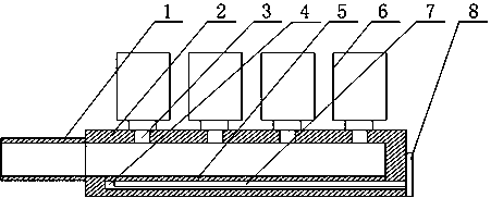
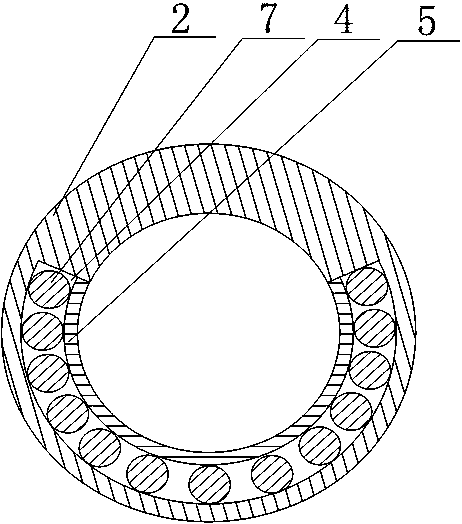
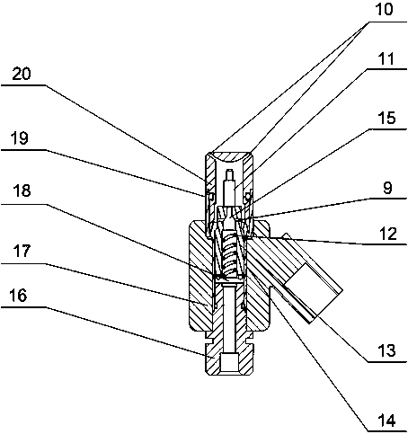
[0026] Such as Figure 1~Figure 3 As shown, this embodiment includes an air intake pipe 1 and a hollow pipe 2 communicating with it. A plurality of injection holes 3 are opened on the upper end of the hollow pipe 2, and a solenoid valve 6 is correspondingly installed on the injection holes 3. The inner wall of the hollow tube 2 is provided with a groove 4 with a superior arc in section, and the injection hole 3 is facing the arc bottom of the groove 4, and a plurality of electric heating tubes 7 are installed in the groove 4, One end of the electric heating tube 7 runs through the end of the hollow tube 2 and is connected to the wiring board 8, and the open end of the groove 4 is covered with a heat conducting plate 5, and the heat conducting plate 5 connects the inside of the groove 4 with the middle. The interior of the empty pipe 2 is separated; the electromagnetic valve 6 includes an electromagnetic valve seat 17 provided with an electromagnetic coil on the inner wall, and...


PUM


Abstract

The invention discloses a liquefied gas stable jetting subsection transporting structure for cars. The liquefied gas stable jetting subsection transporting structure comprises a gas inlet pipe and a hollow pipe, a plurality of jetting holes are formed in the upper end of the hollow pipe, solenoid valves are correspondingly installed on the jetting holes, grooves with major arc cross sections are formed in the inner wall of the hollow pipe, the jetting holes right face the arc bottoms of the grooves, a plurality of electric heating pipes are arranged in the grooves, one end of each electric heating pipe penetrates the end of the hollow pipe to be connected with a connection line insertion plate, a heat conduction plate covers the open end of each groove, and the interiors of the grooves areseparated from the interior of the hollow pipe through the heat conduction plates. Compared with a hydrothermal manner, the adopted electric heating manner avoids the liquid leakage risk, and meanwhile, the heating efficiency is greatly improved; and the multiple electric heating pipes are placed in the arc grooves, the side ends of the grooves are sealed through the connection line insertion plate, heat losing can be reduced, meanwhile, the electric heating pipes can be conveniently taken and placed, in other words, a user can determine the number of the electric heating pipes in real time according to the supply amount of gas, and it is guaranteed that stable operation on gas output flow is achieved with smallest cost.

Description

technical field [0001] The invention relates to a fuel injection rail, in particular to a segmental conveying structure for stable injection of liquefied gas for automobiles. Background technique [0002] The gas injection rail is a necessary equipment on CNG-gasoline dual-fuel vehicles, but when the temperature is low, the low temperature causes the gas in the low-pressure pipeline to shrink, forming a negative pressure between the gas common rail and the filter, so that the gas injection rail opens It is not easy and affects the normal use of the gas system; we use water heating to heat the gas injection rail to make it work normally, but it is necessary to install a waterway, which increases pipeline interference, is prone to liquid leakage, and increases the difficulty of maintenance. Contents of the invention [0003] The purpose of the present invention is to provide a liquefied gas for automobiles with a stable spraying segmental delivery structure to ensure the nor...

Claims


Application Information

Patent Timeline
Patent Type & Authority Applications(China)
IPC IPC(8): F02M21/06F02M21/02
CPCF02M21/0218F02M21/0245F02M21/06Y02T10/30
Inventor 邱晓霞
Owner 邱晓霞
Why Eureka
Try Eureka