
Manufacturing method of special pneumatic valve for automobile

A technology for air pressure valves and automobiles, applied in valve details, valve devices, mechanical equipment, etc., can solve the problem that air pressure valves do not have a variety of flow settings, and achieve the effect of convenient use of the device

Active Publication Date: 2018-03-06
浙江新中南汽车零部件股份有限公司
View PDF4 Cites 0 Cited by
  • Summary
  • Abstract
  • Description
  • Claims
  • Application Information

AI Technical Summary

Problems solved by technology

This air pressure valve does not have the function of setting multiple flow rates

Method used


Image

  • Manufacturing method of special pneumatic valve for automobile
  • Manufacturing method of special pneumatic valve for automobile
  • Manufacturing method of special pneumatic valve for automobile

Examples


Embodiment Construction

[0022] The technical solutions in the embodiments of the present invention will be clearly and completely described below in conjunction with the accompanying drawings in the embodiments of the present invention. Obviously, the described embodiments are only a part of the embodiments of the present invention, rather than all the embodiments. Based on the embodiments of the present invention, all other embodiments obtained by those of ordinary skill in the art without creative work shall fall within the protection scope of the present invention.

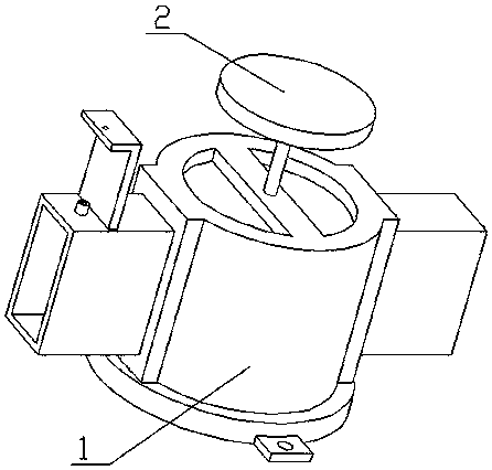
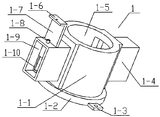
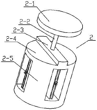
[0023] See Figure 1-5 , The invention provides a technical solution: a method for preparing an automobile-specific air pressure valve, which includes an outer frame 1 and an inner assembly 2. The outer frame 1 includes an outer cylinder 1-1, a bottom plate 1-2, a fixed plate 1-3, Outlet 1-4, outer cylinder slot 1-5, hand plate 1-6, baffle 1-7, screw seat 1-8, air inlet 1-9 and baffle slot 1-10, the bottom plate 1 -2 is connected to the...


PUM


Abstract

The invention discloses a manufacturing method of a special pneumatic valve for an automobile. The special pneumatic valve comprises an outer frame and an inner component, wherein the outer frame comprises an outer tube, a baseplate, fixed plates, an air-out channel, an outer tube groove, a hand plate, a baffle, a screw base, an air inlet channel and a baffle slot; the two fixed plates are connected to the baseplate in a welding manner; a round through hole is formed in each fixed plate; the outer tube is fixedly connected to the upper end of the baseplate; the outer tube groove is formed in the outer tube; the air-out channel is arranged at one end of the outer tube; the air inlet channel is arranged at the other end of the outer tube; the air-out channel, the outer tube and the air inletchannel communicate with one another; the baffle slot is formed in the air inlet channel; the upper end of the baffle slot is an open end; and the baffle is inserted into the baffle slot in an interference fit manner.

Description

Technical field [0001] The invention relates to a pneumatic valve, in particular to a method for preparing a special pneumatic valve for automobiles. Background technique [0002] A load switch pneumatic valve with application number CN201220328527.3. The present invention discloses a load switch pneumatic valve, which includes a valve seat, a valve stud, an end cover, and a spring washer. The spring washer is placed at the bottom of the pneumatic valve. The spring gasket is provided with an end cover, the end cover is connected with a valve stud bolt, the valve stud bolt is set in the valve seat, a rubber O-ring is set between the valve seat and the valve stud bolt, and a spring is set outside the valve stud bolt. In order to prevent the air leakage of the air pressure valve, the air pressure valve has a good sealing effect so that the load switch can work normally. This pneumatic valve does not have the function of setting multiple flow rates. Summary of the invention [000...

Claims


Application Information

Patent Timeline
Patent Type & Authority Applications(China)
IPC IPC(8): F16K31/12F16K5/04F16K5/08
CPCF16K5/0442F16K5/08F16K31/12
Inventor 张开华
Owner 浙江新中南汽车零部件股份有限公司
Learn More