
Propeller test device

A testing device and technology for propellers, applied in the field of propellers, can solve the problems of safety, economy, limitation of testing accuracy, inability to carry out physical tests, etc., and achieve the effects of facilitating promotion, improving testing efficiency, and low manufacturing cost.

Inactive Publication Date: 2018-03-06
天长市星舟航空技术有限公司
View PDF0 Cites 2 Cited by
  • Summary
  • Abstract
  • Description
  • Claims
  • Application Information

AI Technical Summary

Problems solved by technology

Because the air field test is limited by safety, economy and test accuracy, etc.
It is often also required to predict the performance of the full-scale propeller before it is manufactured, and of course it is impossible to carry out physical tests

Method used


Image

  • Propeller test device
  • Propeller test device
  • Propeller test device

Examples


Embodiment 1

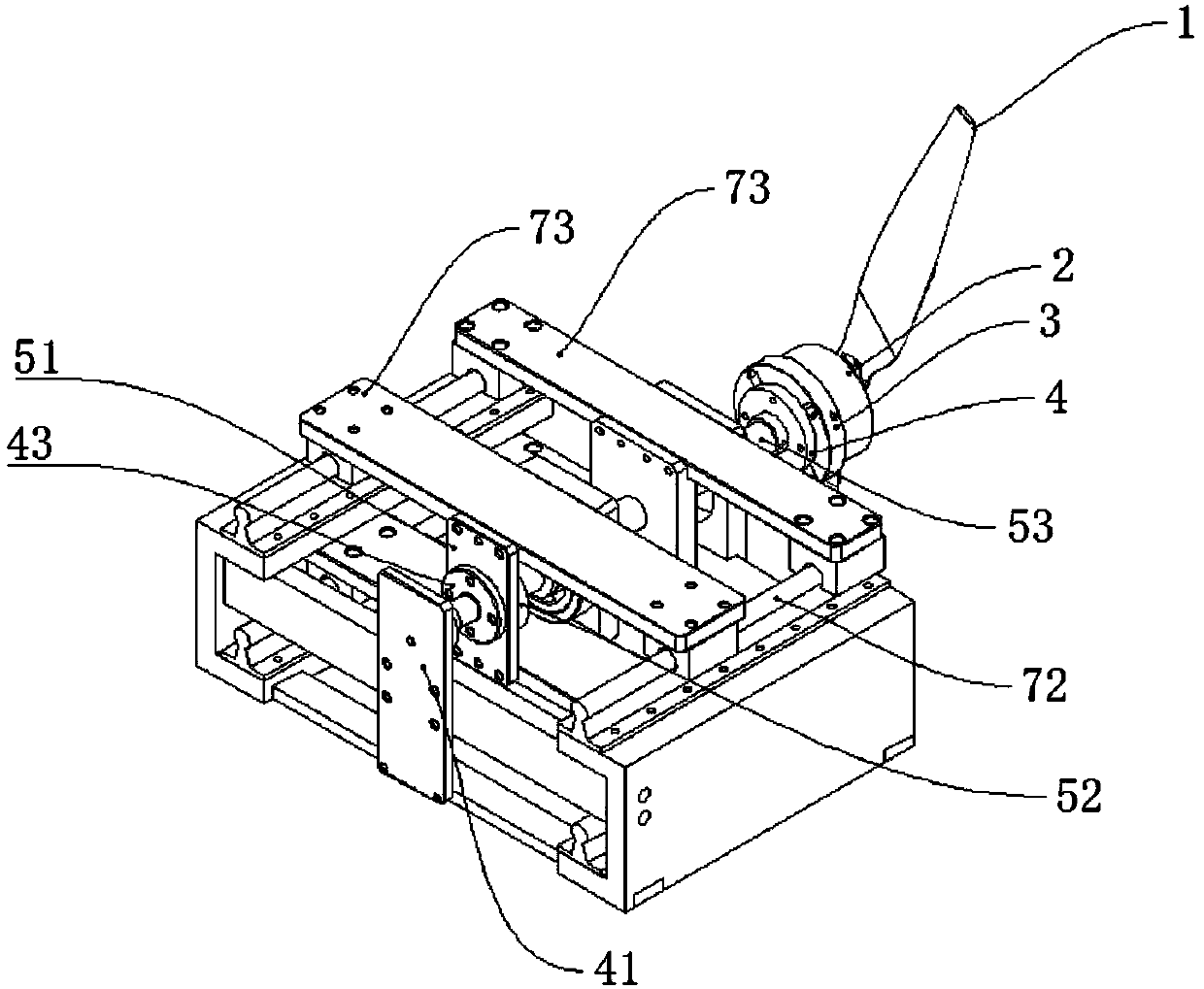
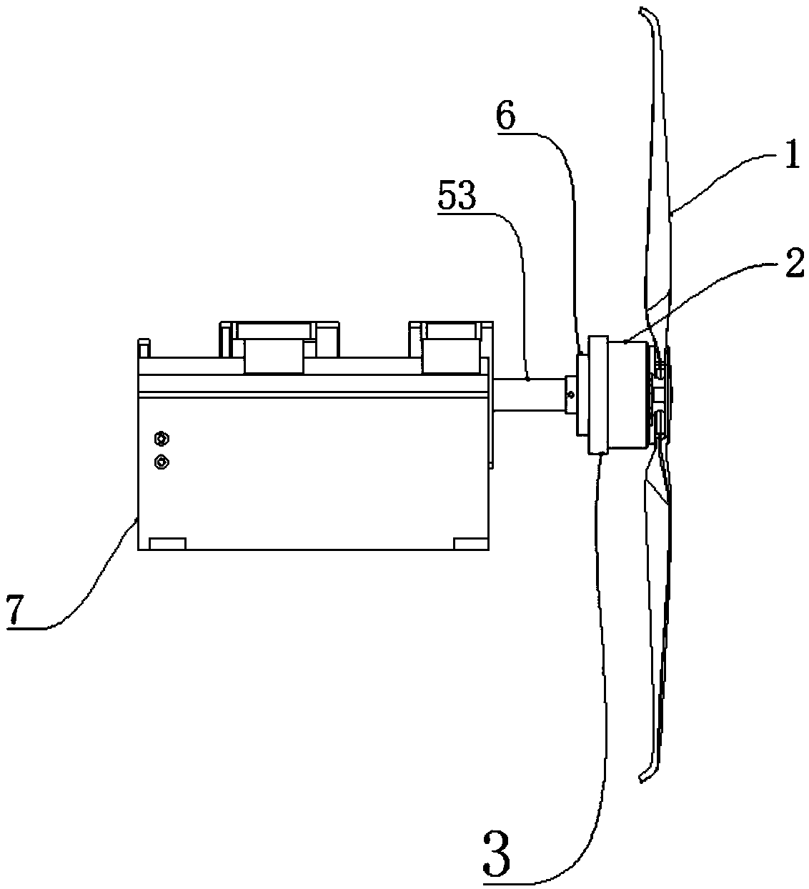
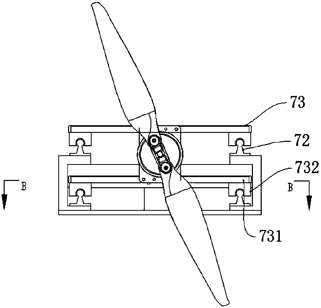
[0029] Such as figure 1 and figure 2 As shown, a propeller test device includes a propeller 1 and a motor 2 arranged at the rear end of the propeller 1 to provide rotational power for the propeller 1. The motor 2 is fixed on the motor base 3, and also includes a mounting frame 7 and is arranged on the mounting frame 7. The tension sensor 4 used to measure the tension parameter, the torque sensor 5 used to measure the torsion parameter, and the shock sensor 6 passing through one end of the mounting frame 7 and fixed on the motor base 3 for measuring the vibration parameter, the tension sensor 4, the torsion force The sensor 5 and the vibration sensor 6 respectively transmit the measured parameters to the display screen 84 arranged on one side of the installation frame 7 via wires.

[0030] In the prior art, the propeller testing machine is generally a single-function device. When testing the motion parameters of the propeller, generally only one of the parameters can be teste...

Embodiment 2

[0039] The structure of this embodiment is basically the same as the structure of Embodiment 1, and the similarities will not be repeated. The difference is that: Figure 7 , Figure 8 As shown, the propeller testing machine is arranged in the wind tunnel device 8, the wind tunnel device 8 includes a box body 81 and a wind tunnel 82 arranged in the box body 81 for testing the performance of the propeller 1, and two horizontally arranged in the wind tunnel 82 for The supporting beam 83 supporting the fixed installation frame 7 is provided with a display screen 84 for reflecting test parameters on one side of the box body 81, and a transformer cover 85 for installing a transformer is provided on the upper side of the box body 81, so that the gas can be studied through the wind tunnel device 8. Flow and its interaction with the propeller 1, in order to understand the aerodynamic characteristics of the actual propeller 1, the experimental conditions can be controlled more accurate...


PUM


Abstract

The present invention relates to the field of propellers, more specifically, to a propeller testing device, comprising a mounting frame, a tension sensor arranged on the mounting frame for measuring tension parameters, a torsion sensor for measuring torsion parameters, and a thread through one end of the mounting frame. and fixed on the base of the motor for measuring the vibration parameters of the vibration sensor, the tension sensor, torque sensor and vibration sensor respectively transmit the measured parameters to the display screen arranged on one side of the mounting bracket via wires, so, in The tensile performance, torsion performance and vibration performance of the propeller can be tested simultaneously on the same testing machine. Compared with other testing machines that can only test one of the performances, the testing efficiency is greatly improved. At the same time, the testing machine provided by the invention has a simple structure , the manufacturing cost and volume are lower than the total cost and total volume of three single-function testing machines that achieve the same testing purpose, making the propeller testing device more competitive in the market.

Description

Technical field: [0001] The present invention relates to the field of propellers, more specifically, to a propeller testing device. Background technique: [0002] A propeller refers to a device that converts the rotational power of the drive device into propulsion by the blades rotating in the air or water. It is widely used in propellers such as aircraft, ships, aircraft, and aerostats. [0003] Although aviation propulsion technology has already entered the jet age, the propeller, an aerodynamic component that plays an important role in the history of aviation development and generates pulling force, has not left this field. At present, most regional aircraft, general aviation aircraft and almost all civil aircraft developed in our country, especially most of the unmanned aerial vehicles in our country still use propellers as tensile components. The performance calculation of the propeller is the most important part in the design and application of the propeller. When des...

Claims


Application Information

Patent Timeline
Patent Type & Authority Applications(China)
IPC IPC(8): G01M13/00
CPCG01M13/00
Inventor 李金龙
Owner 天长市星舟航空技术有限公司
Learn More