
Auto-buckled motor core laminated riveting force testing mechanism and method
A testing mechanism and iron core technology, applied in the direction of applying stable tension/pressure to test the strength of materials, measuring devices, instruments, etc., can solve the problems of high operating ability requirements, easy instability of punching sheets, and affecting test accuracy, etc., to achieve The consistency of the screw-in depth is good, the precision of the tensile test is high, and the effect of improving the test accuracy
- Summary
- Abstract
- Description
- Claims
- Application Information
AI Technical Summary
Problems solved by technology
Method used
Image

Examples
Embodiment
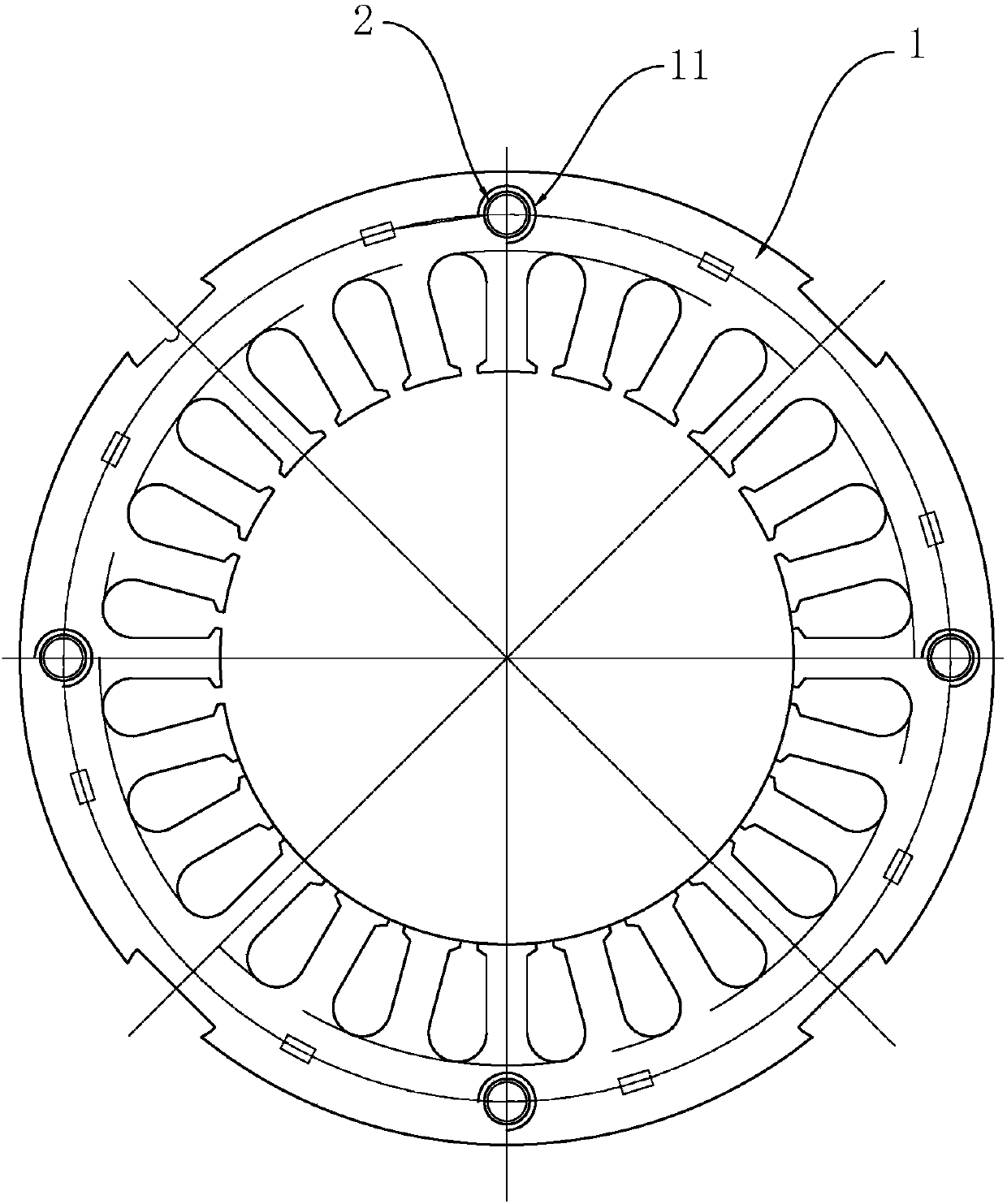
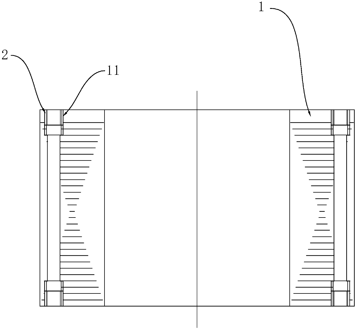
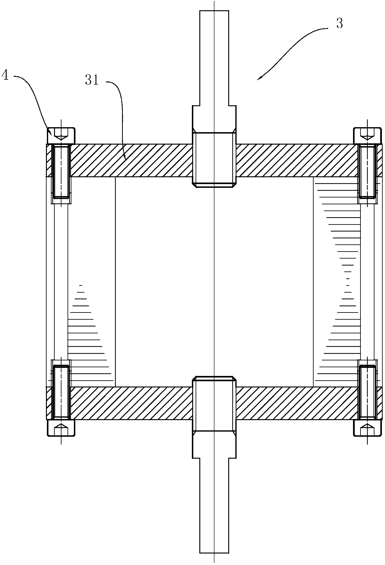
[0050] Example: such as Figure 1-Figure 3 As shown, the motor self-fastening iron core stack riveting force testing mechanism includes a wire screw sleeve and a tensile tooling. The self-fastening iron core 1 is provided with an axial wire screw sleeve fitting hole 11, and the wire screw sleeve 2 is arranged on The steel wire screw set fitting holes 11 are screwed to the steel wire screw set fitting holes. The bottom plates 31 of the stretching tooling 3 are respectively buckled on the two ends of the self-fastening iron core, and passed through by the screws 4. The bottom plate corresponds to the inner hole of the wire screw sleeve, and forms a one-to-one corresponding screw connection with the wire screw sleeve.
[0051] Fit the steel wire screw into the hole of the steel wire screw, and then fix the test work to the iron core through the screw matched with the steel wire screw, so as to overcome the unfavorable situation caused by the direct cooperation of the screw with t...
PUM
| Property | Measurement | Unit |
|---|---|---|
| thickness | aaaaa | aaaaa |
Abstract
Description
Claims
Application Information