A sensorless permanent magnet synchronous motor rotor position detection method

Active Publication Date: 2019-11-22
NORTHWESTERN POLYTECHNICAL UNIV
View PDF5 Cites 0 Cited by
  • Summary
  • Abstract
  • Description
  • Claims
  • Application Information

AI Technical Summary

Problems solved by technology

This type of method can estimate the rotor position at low speed or even zero speed, but when the motor is running in the high-speed area, the back electromotive force is too large, and the rotation component in the voltage equation cannot be ignored, which reduces the accuracy of position estimation and deteriorates the stability.

Method used


Image

  • A sensorless permanent magnet synchronous motor rotor position detection method
  • A sensorless permanent magnet synchronous motor rotor position detection method
  • A sensorless permanent magnet synchronous motor rotor position detection method

Examples


Embodiment Construction

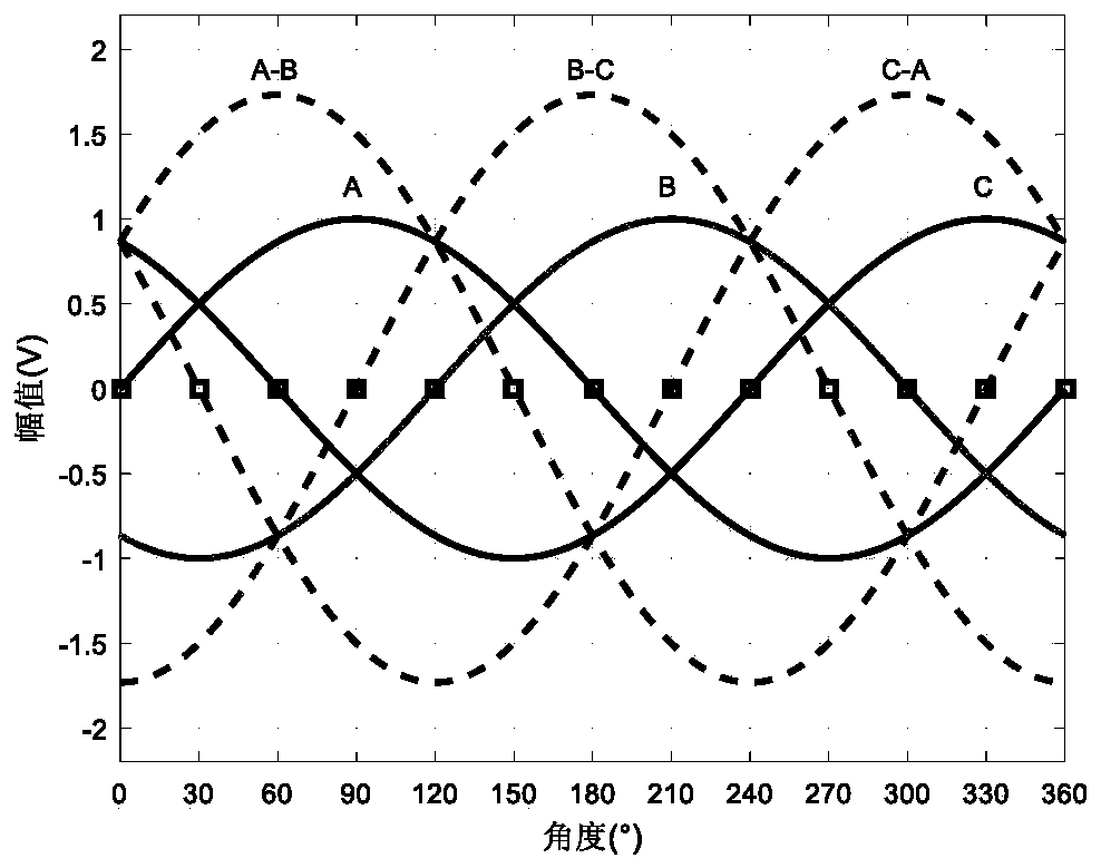
[0033] During the rotation of the permanent magnet synchronous motor rotor, the winding will generate a back electromotive force due to cutting the magnetic force line, and the back electromotive force has a direct correspondence with the rotor phase, so the back electromotive force information can be used to monitor the phase of the rotor. During the operation of the motor, the amplitude of the reverse electromotive force is used to determine the phases of the rotor. The implementation method is complicated. On the one hand, there are high-frequency components in the currents of each phase. On the other hand, when the speed is unstable, the back electromotive force itself is also unstable. Therefore, it is not suitable to convert the rotor phase directly from the magnitude of the back electromotive force. The method of signal processing can be used to digitally process the change process of the back electromotive force of the three-phase winding, and extract some relatively sta...


PUM


Abstract

The invention relates to a method for detecting the position of a rotor of a PMSM (permanent magnet synchronous motor) without a position sensor, and the method comprises the steps: employing a signalprocessing method for the digital processing of a change process of the back electromotive force of a three-phase winding; extracting some relatively reliable feature position of the back electromotive force in the rotating process of the motor, such as a zero point and extreme points; obtaining the position feature points, and carrying out the estimation of the rotor position information betweenthe feature points through an extended Kalman filtering method, and finally obtaining the accurate position of the rotor. The method is convenient in data collection, is small in calculation burden,is good in real-time performances, and is suitable for the implementation of various types of motor controllers.

Description

technical field [0001] The invention relates to a method for detecting the rotor position of a permanent magnet synchronous motor without a position sensor, and belongs to the technical field of motor control. Background technique [0002] For permanent magnet synchronous motors to operate stably, the position of the permanent magnet rotor must be detected in real time to achieve closed-loop control. In order for the permanent magnet synchronous motor to operate in a closed loop, the drive system must know the magnetic pole position of the permanent magnet rotor in real time. Only in this way can the precise control of speed and current be satisfied, so the acquisition of rotor position and speed signals is a very important link in the entire drive system. [0003] The high-precision permanent magnet synchronous motor system puts forward high requirements for speed control and position control, and the requirements for sensors are also increased accordingly. Due to the ins...

Claims


Application Information

Patent Timeline
Patent Type & Authority Patents(China)
IPC IPC(8): H02P6/182H02P21/13H02P21/18
CPCH02P6/182H02P21/13H02P21/18
Inventor 高田薛峰羊彦
Owner NORTHWESTERN POLYTECHNICAL UNIV
Why Eureka
Try Eureka