Braking part and oil wiping device used for same

A technology for brake parts and oil parts, applied in the direction of brake parts, brake parts, valve devices, etc., can solve the problems of heavy oil rubbing workload such as guide rails, affecting the friction braking mechanism, and high safety risks in working conditions, etc. Achieve the effect of reducing labor intensity, reducing the risk of safety devices, and simple structure

Pending Publication Date: 2018-03-09
HANGZHOU HUNING ELEVATOR PARTS CO LTD
View PDF18 Cites 0 Cited by
  • Summary
  • Abstract
  • Description
  • Claims
  • Application Information

AI Technical Summary

Problems solved by technology

[0004] The invention provides a brake piece and an oil wiping device for the brake piece, which solves the problems of large and incomplete oil wiping work such as guide rails, frictional braking mechanism and working conditions during braking that are affected during the braking process. high security risks

Method used


Image

  • Braking part and oil wiping device used for same
  • Braking part and oil wiping device used for same
  • Braking part and oil wiping device used for same

Examples


Embodiment 1

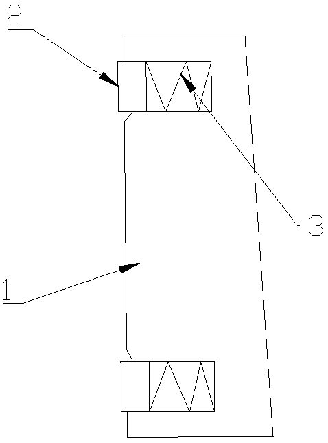
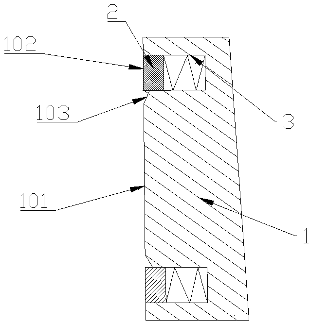
[0033] see figure 1 , 2 , the brake member 1 with oil wiping function in this embodiment forms two installation holes, the installation holes are connected with the outside world through the braking friction surface 101 of the brake member 1, and the opening of the installation hole is equipped with an oil wiper 2 (such as a sponge Body, fiber, rubber, polyurethane), the elastic member 3 (such as a spring) is installed between the inner surface of the oil wiper 2 and the inner bottom surface of the installation hole, the outer surface 102 of the oil wiper 2 protrudes from the installation hole and the outer surface is positive For counterparts (such as guide rails).

[0034] The lower edge of the opening of the upper mounting hole of the brake member 1 is chamfered to form an oil discharge groove 103; the upper edge of the opening of the lower mounting hole is also chamfered to form another oil discharge groove. Both ends of the oil discharge groove extend to both sides of t...

Embodiment 2

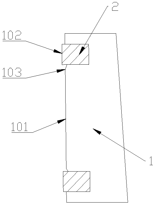
[0037] see image 3 , the braking member 1 of the present embodiment forms two mounting holes, the mounting holes communicate with the outside world through the braking friction surface 101 of the braking member 1, the mounting holes are filled with elastic oil wiper 2 (such as rubber), and the elastic oil wiper 2 The outer side 102 protrudes from the mounting hole.

[0038] The lower edge of the opening of the upper mounting hole of the braking member 1 is chamfered to form an oil discharge groove 103; the upper edge of the opening of the lower mounting hole is also chamfered to form an oil discharge groove. Both ends of the oil discharge groove extend to both sides of the brake piece 1 .

[0039] Under normal circumstances, the elastic oil wiper 2 is in a non-compressed state, and the outer surface of the elastic oil wiper 2 protrudes from the braking friction surface 101 of the brake piece 1; when braking, the elastic oil wiper 2 is first compressed, and the elastic Under...

Embodiment 3

[0041] see Figure 4 , The difference between this embodiment and Embodiment 2 is that this embodiment only has one elastic oil wiper 2 .

[0042] Other content of this embodiment can refer to Embodiment 2.


PUM


Abstract

The invention discloses a braking part and an oil wiping device used for the same. The oil wiping device used for the braking part comprises a support; the supporting is provided with a braking friction face; a mounting hole is formed in the support and communicates with the outside world through the braking friction face; a one-way valve is arranged in the mounting hole of the support and partitions the mounting hole into two spaces; the inner side space of the mounting hole is used for containing scrubbing liquid, and the scrubbing liquid can flow to the outer side space of the mounting holethrough the one-way valve; the inner side space of the mounting hole communicates with the outside world through a guide hole or a conduit; and a movable type oil wiping piece is mounted on the outerside space of the mounting hole, and the outer side face of the oil wiping piece protrudes out of the braking friction face. The oil stain problem of an existing safety protection device in the working state is solved, and the oil wiping device has the advantages of reducing labor intensity, improving braking stability and improving safety protection performance.

Description

technical field [0001] The invention belongs to the technical field of machinery, and in particular relates to a brake piece with an oil wiping function and an oil wiping device for the brake piece. Background technique [0002] In order to prevent rust, the guide rails for elevators are treated with anti-rust treatment on their surfaces when they leave the factory. After installation, the wet guide rails are lubricated on the surface to reduce friction. Devices such as the accidental movement protection of the car prevent accidents by frictional braking with the guide rail. The safety protection device acting on the guide rail needs to remove the anti-rust oil or lubricating oil to achieve a stable braking effect, and different oil types and oil quality or environmental conditions will affect the friction coefficient during braking to varying degrees. The braking of the safety protection device under working conditions has certain safety risks. On the other hand, the anti...

Claims


Application Information

Patent Timeline
Patent Type & Authority Applications(China)
IPC IPC(8): B66B7/12B66B5/18F16D65/02F16K15/04
CPCF16D65/0037F16D65/02F16K15/044B66B5/18B66B7/1292
Inventor 邹家春姚荣康何新
Owner HANGZHOU HUNING ELEVATOR PARTS CO LTD
Why Eureka
Try Eureka