Textile industry waste heat recovery system with automatic cleaning and fire extinguishing functions

A waste heat recovery system and automatic cleaning technology, which is applied in the direction of cleaning heat transfer devices, lighting and heating equipment, washing, etc., can solve the problems of increased power consumption of fans, decreased heat exchange efficiency, and waste of heat energy, etc., to prevent blockage of cooling fins , Improve the efficiency of waste heat recovery and ensure the effect of cooling efficiency

A waste heat recovery system and automatic cleaning technology, which is applied in the direction of cleaning heat transfer devices, lighting and heating equipment, washing, etc., can solve the problems of increased power consumption of fans, decreased heat exchange efficiency, and waste of heat energy, etc., to prevent blockage of cooling fins , Improve the efficiency of waste heat recovery and ensure the effect of cooling efficiency

CN112964103APending Publication Date: 2021-06-15竹校忠

Image

  • Textile industry waste heat recovery system with automatic cleaning and fire extinguishing functions
  • Textile industry waste heat recovery system with automatic cleaning and fire extinguishing functions
  • Textile industry waste heat recovery system with automatic cleaning and fire extinguishing functions

Examples


Embodiment 1

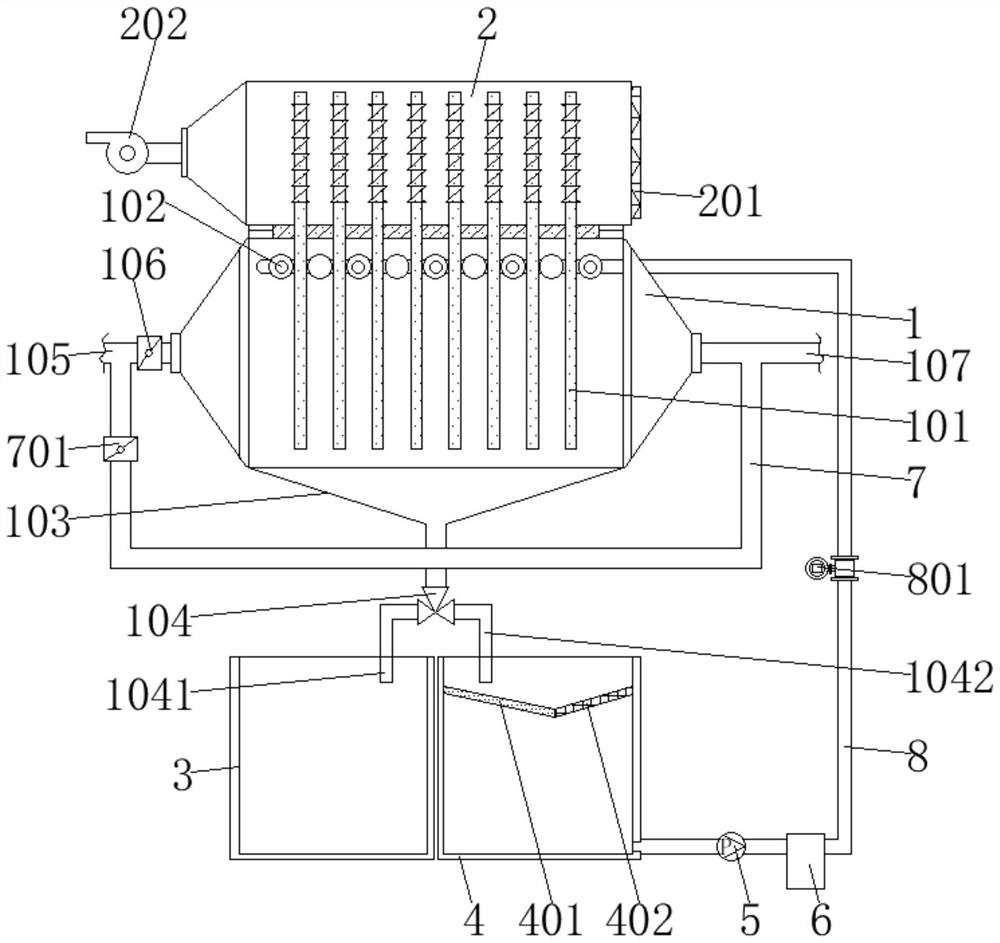
[0032] Such as figure 1 As shown, a waste heat recovery system for the textile industry with automatic cleaning and fire extinguishing functions, including a flue gas chamber 1, a waste heat recovery chamber 2, an oil storage tank 3, a cleaning liquid tank 4, a pump 5, a filter 6, and a flue gas chamber 1 is fixed with a plurality of heat pipes 101, and the top of the flue gas chamber 1 is horizontally arranged with a number of hollow shower heads 102. The bottom is fixed with a diversion bucket 103, and the bottom port of the diversion bucket 103 is connected with a sewage collection switching valve 104 through a conduit. The left and right sides of the sewage collection switching valve 104 are equipped with a first discharge short pipe 1041 and a second discharge short pipe 1041. The short pipe 1042, the air inlet pipe 105 is installed at the air inlet end of the left outer wall of the smoke chamber 1, and the fire damper 106 is installed at the end of the air inlet pipe 105...

Embodiment 2

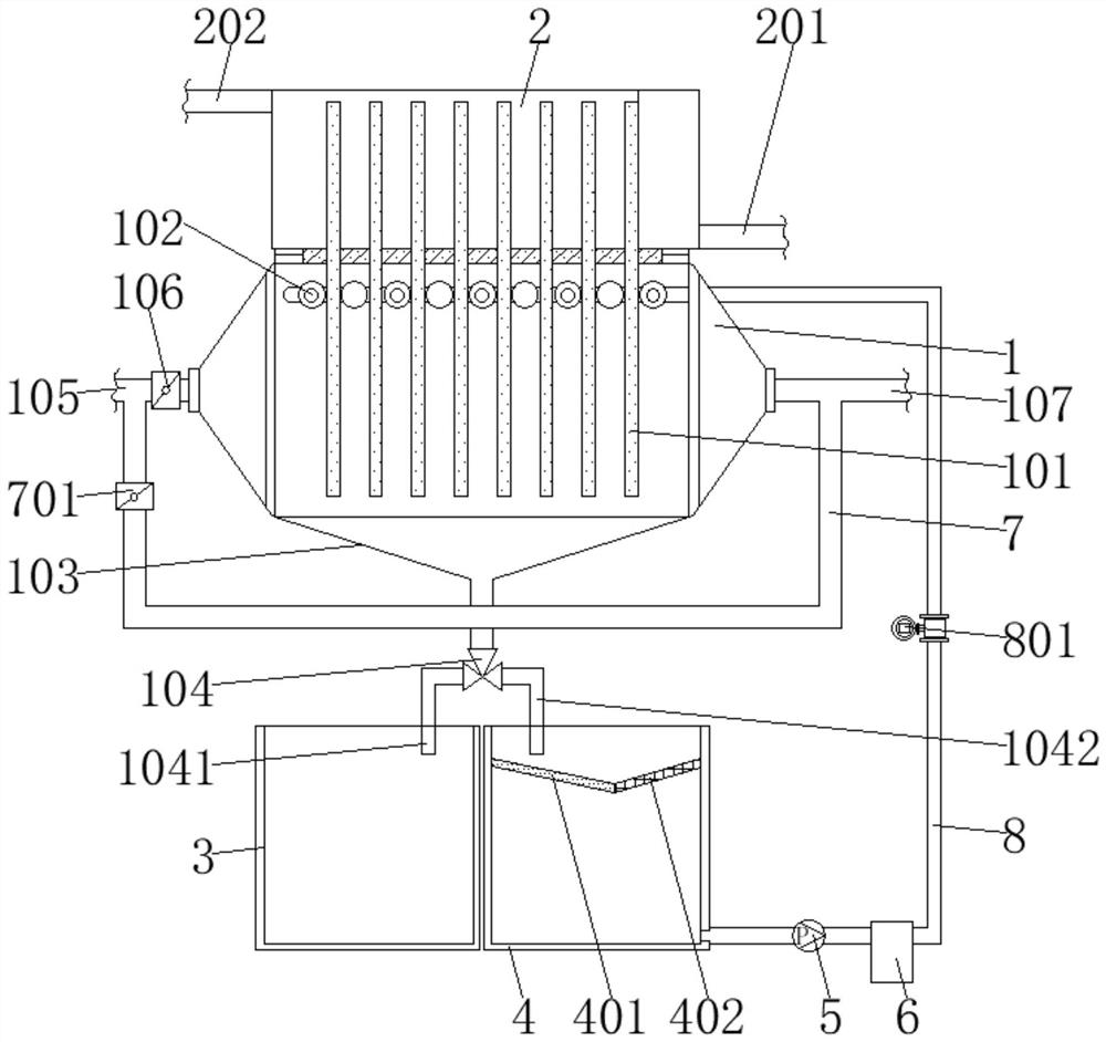
[0047] Such as figure 2 As shown, a waste heat recovery system for the textile industry with automatic cleaning and fire extinguishing functions, including a flue gas chamber 1, a cooling water chamber 2, an oil storage tank 3, a cleaning liquid tank 4, a pump 5, a filter 6, and a flue gas chamber 1 is fixed with a plurality of heat pipes 101, and the top of the flue gas chamber 1 is horizontally arranged with a number of hollow shower heads 102. The bottom is fixed with a diversion bucket 103, and the bottom port of the diversion bucket 103 is connected with a sewage collection switching valve 104 through a conduit. The left and right sides of the sewage collection switching valve 104 are equipped with a first discharge short pipe 1041 and a second discharge short pipe 1041. The short pipe 1042, the air inlet pipe 105 is installed at the air inlet end of the left outer wall of the smoke chamber 1, and the fire damper 106 is installed at the end of the air inlet pipe 105 clos...


PUM


Abstract

The invention discloses a textile industry waste heat recovery system with automatic cleaning and fire extinguishing functions. The system comprises a flue gas cavity, a waste heat recovery cavity, an oil stain storage box, a cleaning liquid box, a pump and a filter, a plurality of heat pipes are fixedly arranged in the flue gas cavity, a plurality of hollow spray heads are horizontally arranged at the top end in the flue gas cavity, a flow guide hopper is fixedly arranged at the bottom of the flue gas cavity, a bottom through opening of the flow guide hopper is connected with a sewage collection conversion valve through a guide pipe, through openings in the left side and the right side of the sewage collection conversion valve are provided with a first discharge short pipe and a second discharge short pipe, and a gas inlet pipe is installed at the gas inlet end of the outer wall of the left side of the flue gas cavity. According to the textile industry waste heat recovery system with the automatic cleaning and fire extinguishing functions, the problem that the heat exchange efficiency is greatly reduced due to the fact that greasy dirt is coked on the heat exchange surface is solved, the heat exchange efficiency is improved, the problem of fire can be prevented, and certain use value and popularization value are achieved.

Description

technical field [0001] The invention relates to the technical field of waste heat recovery, in particular to a waste heat recovery system for the textile industry with automatic cleaning and fire extinguishing functions. Background technique [0002] In the textile industry, especially the printing and dyeing industry, the temperature of the flue gas discharged from the drying, setting and other processes is relatively high, especially the setting machine, the exhaust gas temperature is as high as 150°C-210°C, and these flue gases enter the Industrial oil fume purifiers cause a lot of waste of heat energy, and cause excessive cooling water consumption and poor treatment effects for industrial oil fume purifiers; the existing waste heat recovery systems use shell and tube heat exchange, heat pipe type For heat exchange, even heat pump heat exchange, the above heat exchange methods are relatively effective when newly installed, but after a period of use, due to the coking of o...

Claims


Application Information

Patent Timeline
15 Jun 2021
Publication
CN112964103A
IPC
F28D15/02; F28F1/12; F28F19/01; F28F19/02; F28G9/00; F28G15/00; A62C31/00
CPC
A62C31/005; A62C99/0072; F28D15/0266; F28F1/12; F28F19/01; F28F19/02; F28G9/00; F28G15/00
Inventors
竹校忠