A Mechanical Shutter for Vacuum Environments

A mechanical shutter and vacuum environment technology, applied in the field of photography, can solve problems such as exposure errors, difficulty in meeting size requirements, and large shutter size, and achieve the effects of wide application, high reliability, and protection

Active Publication Date: 2021-07-09
PEKING UNIV
View PDF12 Cites 0 Cited by
  • Summary
  • Abstract
  • Description
  • Claims
  • Application Information

AI Technical Summary

Problems solved by technology

[0005] The traditional mechanical shutter driving method is mostly motor-driven, but the motor structure often contains lubricating grease, and the lubricating grease will volatilize in a vacuum environment, and the volatilized organic matter will diffuse in the vacuum and will pollute optical devices (such as optical lenses, gratings, etc.) Surface, seriously affect the effect of optical experiments, and even damage optical devices
In addition, most of the mechanical shutters driven by motors control the exposure time by adjusting the stepping amount of the motor in conjunction with the spring or mechanical transmission structure. When the exposure time needs to be adjusted, due to the many components involved and the many influencing factors, repeated testing and adjustments are required. In order to achieve the expected exposure time, the operation is cumbersome when using
[0006] In addition, traditional mechanical shutters usually move the shading plate through connecting rods, ratchets, rotation and other structures. This kind of shutter opening and closing structure is relatively complicated, resulting in a large shutter size, which is difficult to meet the size requirements of optical experiments in a small space.
[0007] In the prior art, there are also mechanical shutters that use electromagnetic drive and rotary transmission to control the movement of the shading plate, such as the invention patent with application number 201110444477.5, but this design has a large rotating space, which is not conducive to the control of the size of the shutter, and the shading plate The uneven magnetic field force received makes it difficult to control the rotation speed, and it is difficult to achieve precise control of the exposure time. There are also many uncertainties in the reset process. Exposure errors, and even damage to the camera

Method used


Image

  • A Mechanical Shutter for Vacuum Environments
  • A Mechanical Shutter for Vacuum Environments
  • A Mechanical Shutter for Vacuum Environments

Examples


Embodiment Construction

[0048] The present invention will be described in further detail below by means of the accompanying drawings. Through these descriptions, the features and advantages of the present invention will become more apparent.

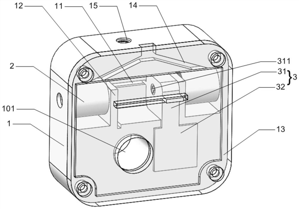
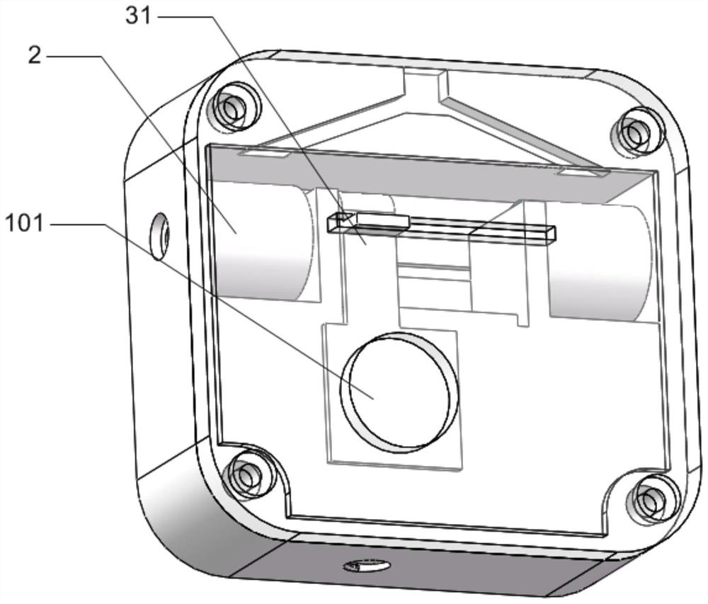
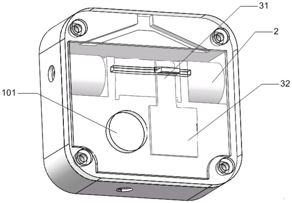
[0049] The present invention provides a kind of mechanical shutter that is used for optical experiment of high vacuum environment, comprises shutter base 1, is provided with light through hole 101 on shutter base 1, as figure 1 shown.

[0050] The light hole 101 passes through the shutter base 1 , and the electromagnet 2 and the light shielding part 3 are arranged in the shutter base 1 , and the permanent magnet 311 is arranged on the light shielding part 3 .

[0051] In the present invention, the light-shielding part 3 is driven electromagnetically instead of the traditional motor drive, which solves the problems that the motor lubricating grease volatilizes in a vacuum and affects the experimental results and contaminates the optical devices.

[0052] The l...


PUM


Abstract

The invention discloses a mechanical shutter used in a vacuum environment, which comprises a shutter base (1), on which a light hole (101) is arranged, and an electromagnet (2) is arranged inside the shutter base (1). ) and light-shielding part (3), light-shielding part (3) has driving part (31) and light-shielding plate (32), permanent magnet (311) is set on driving part (31), electromagnet (2) magnetic pole points to permanent magnet ( 311). The mechanical shutter used in the vacuum environment of the present invention has many advantages such as simple structure, small size, no pollution, high reliability, and response speed up to millisecond level.

Description

technical field [0001] The invention relates to a mechanical shutter, in particular to a mechanical shutter used in a high-vacuum environment, and belongs to the field of imaging. Background technique [0002] In some optical experiments, it is necessary to use the camera to collect the imaging information of light to obtain experimental data. The mechanical shutter is a key device to control the exposure time of the camera, which has a direct impact on the imaging quality of the camera. [0003] The optical experiment environment is different from the conventional camera environment. In addition to the extremely high requirements for shutter response time and action time, in optical experiments using high-energy lasers, the laser can reach TW or even PW levels. Under such high-energy lasers, the camera Directly receiving high-energy laser signals will cause damage to it. In order to avoid "accidental damage" to the camera by high-energy laser, it is necessary to use a mecha...

Claims


Application Information

Patent Timeline
Patent Type & Authority Patents(China)
IPC IPC(8): G03B9/08
CPCG03B9/08
Inventor 苏育民寿寅任曹正轩马文君
Owner PEKING UNIV
Why Eureka
Try Eureka