
A flexible winding deformation simulation device

A winding deformation and simulation device technology, applied in the direction of measuring devices, measuring electrical variables, instruments, etc., can solve problems such as difficulties, failure to consider inner layer winding deformation, difficulty in recovery, etc.

Active Publication Date: 2020-07-10
ELECTRIC POWER RES INST OF GUANGXI POWER GRID CO LTD
View PDF3 Cites 0 Cited by
  • Summary
  • Abstract
  • Description
  • Claims
  • Application Information

AI Technical Summary

Problems solved by technology

[0005] The winding deformation is simulated by the equivalent circuit of capacitance, inductance, and resistance elements, as shown in CN202887569U and CN204347165U, but this method is difficult to take into account the actual influence of leakage inductance, iron core nonlinearity, etc., and cannot fit the reality, and is not accurate enough. The deformation of the winding of the true transformer mainly includes CN105526835A, which converts the distributed capacitance change caused by the radial deformation of the winding into the distributed capacitance change caused by the deformation of the oil tank, and changes the position of the deformation block, which is equivalent to changing the position of the winding deformation. Or the range and degree of deformation of the winding are changed, but this method only considers the capacitance change of the outer layer of the winding, and fails to consider the deformation of the inner layer winding and the deformation between the windings, and the model is not accurate enough
Moreover, it is difficult to make the deformed state of the winding of the existing simulation device and it is difficult to recover, which has caused obstacles and difficulties for the deformation of multiple windings.

Method used


Image

  • A flexible winding deformation simulation device
  • A flexible winding deformation simulation device
  • A flexible winding deformation simulation device

Examples


Embodiment Construction

[0024] The following will clearly and completely describe the technical solutions in the embodiments of the present invention with reference to the drawings in the embodiments of the present invention. Apparently, the described embodiments are only some of the embodiments of the present invention, but not all of them. Based on the embodiments of the present invention, all other embodiments obtained by persons of ordinary skill in the art without creative efforts fall within the protection scope of the present invention.

[0025] In the description of the present invention, it should be noted that the orientation or positional relationship indicated by the term "inner" is based on the orientation or positional relationship shown in the drawings, or the orientation or positional relationship that is usually placed when the product of the invention is used , is only for the convenience of describing the present invention and simplifying the description, but does not indicate or i...


PUM


Abstract

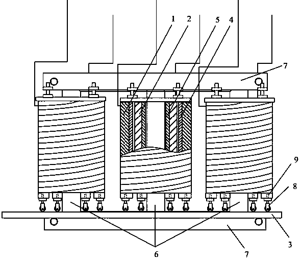
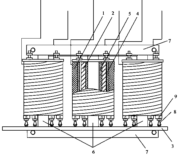
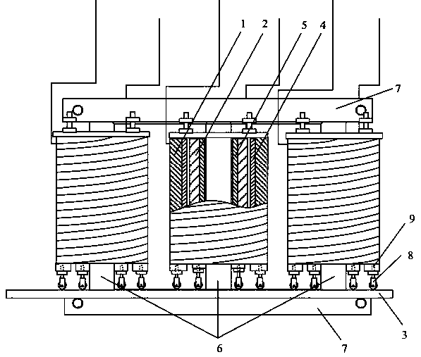
The invention discloses a flexible winding deformation simulation device which mainly comprises a high-voltage winding, a low-voltage winding, a bottom plate, a high-voltage winding bracket, a low-voltage winding bracket, an iron core and clamps. By virtue of the characteristics that a flexible winding is liable to deform and recover and a bracket can be moved horizontally, deformation simulationon displacement, partial deformation, interturn short circuits and the like of a transformer can be achieved by changing the shape and / or adjusting the position of the flexible winding. Deformation situations of different parts and different shapes of the transformer are taken into account sufficiently, and a novel method for simulating actual winding deformation is provided; winding deformation includes most types of conventional transformer winding deformation, testing targets are provided for short circuit impedance testing and frequency response method testing, and calibration samples areprovided for testing instruments; and under the condition that a winding is not disassembled or pulled out, winding deformation of different shapes at different parts can be caused, and the device hasthe advantages of accuracy, reality, flexibility, visibility and reutilization.

Description

technical field [0001] The invention relates to a flexible winding deformation simulation device. Background technique [0002] Power transformers are one of the most important equipment in power plants and substations, and their safety has an important impact on power grids and social stability. It is difficult for the transformer to withstand various short-circuit faults during the operation of the system. The short-circuit current can reach 10 to 20 times the rated current of the transformer. This current will generate a huge mechanical force in the transformer winding. This is the main reason for the mechanical deformation of its windings, and the accumulation of deformation is one of the important reasons for accidents in transformers and power systems. For transformers with loose windings, when the looseness does not endanger the insulation, the total hydrocarbons and components in the oil remain normal. The inspection of the hanging core is the simplest and most intu...

Claims


Application Information

Patent Timeline
Patent Type & Authority Patents(China)
IPC IPC(8): G01R35/00
CPCG01R35/007
Inventor 陈梁远余长厅黎大健赵坚张玉波张磊苏星华蒲金雨颜海俊
Owner ELECTRIC POWER RES INST OF GUANGXI POWER GRID CO LTD
Learn More