
Punching force adjustable punching machine

An adjustable, punching machine technology, applied in the direction of presses, punching machines, manufacturing tools, etc., can solve the problems of increasing equipment floor space, increasing operating stations, increasing processing equipment, etc., to reduce floor space and reduce operations. The effect of station, improved stamping quality and stamping efficiency

Inactive Publication Date: 2018-03-13
芜湖尚唯汽车饰件有限公司
View PDF7 Cites 0 Cited by
  • Summary
  • Abstract
  • Description
  • Claims
  • Application Information

AI Technical Summary

Problems solved by technology

[0004] The present invention aims at changing the performance of stamping parts by using low-frequency stamping in the processing of small parts in existing stamping machines, which is difficult, has many defects such as increasing processing equipment, increasing equipment footprint, increasing operating stations, etc., and the production cost is therefore large. Insufficiencies such as the increase in the amplitude and the impact on the processing efficiency after the process is dispersed, a fixed device for the stamping head of the automobile mold is proposed, which can further improve the stamping quality and stamping efficiency of the stamping parts

Method used


Image

  • Punching force adjustable punching machine

Examples


Embodiment Construction

[0014] The present invention will be further described below in conjunction with accompanying drawing:

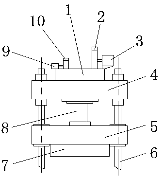
[0015] Such as figure 1 As shown, the punching pressure adjustable punching machine includes an upper beam 4, a column 6, an upper stamping die 7 and a slider 5, a telescopic rod 8 is connected between the upper beam 4 and the slider 5, and the upper punching die 7 is arranged on The bottom of the slide block 5; the top of the upper beam 4 is provided with a control device 1, the top of the control device 1 is provided with a first drive motor 3 and a second drive motor 9, the first drive motor 3 is provided with a large cam mechanism 2, and the second The drive motor 9 is provided with a small cam mechanism 10, and the cams in the large cam mechanism 2 and the small cam mechanism 10 are all connected to the telescopic rod 8. The first drive motor 3 and the second drive motor 9 form a connection circuit with the control device 1 .

[0016] Such as figure 1 As shown, in t...


PUM


Abstract

The invention discloses a punching force adjustable punching machine, and belongs to the technical field of automobile die processing. The punching force adjustable punching machine comprises an upperbeam, a vertical column, an upper punching die and a slider, a telescopic rod is connected between the upper beam and the slider, the upper punching die is arranged at the bottom of the slider, a control device is arranged on the upper portion of the upper beam, a first driving motor and a second driving motor are arranged on the upper portion of the control device, a large cam mechanism is arranged on the first driving motor, a small cam mechanism is arranged on the second driving motor, cams in the large cam mechanism and the small cam mechanism are connected with the telescopic rod in an acting manner, and the first driving motor and the second driving motor form connection loops together with the control device. The punching force adjustable punching machine is novel in structure andclear in working principle, the control device controls running and stopping of the first driving motor and the second driving motor, and the speed of the telescopic rod is adjusted by curves of the cams in the large cam mechanism and the small cam mechanism. Compared with a traditional punching structure, the punching force adjustable punching machine has the advantages that punching force can beselected in a targeted manner according to the sizes and materials of parts to be punched, and the punching quality and the punching efficiency of punched parts can be further improved.

Description

technical field [0001] The invention belongs to the technical field of automobile mold processing, and relates to a punching machine, in particular to a punching pressure adjustable punching machine. Background technique [0002] With the continuous development of modern technology, many automotive products are made of metal materials. Because the metal is relatively hard, it can protect the internal components very well. At present, when factories process these shells, they often use stamping to stamp the metal sheet into the required shape. [0003] The current stamping machine consists of two parts, respectively including a conveying mechanism and a stamping mechanism. The stamping mechanism includes an upper die and a lower die. The upper die is then moved towards the lower die, which punches the sheet into the desired shape. Existing stamping machines usually change the stamping frequency to adapt to the processing of large and small parts during the processing proces...

Claims


Application Information

Patent Timeline
Patent Type & Authority Applications(China)
IPC IPC(8): B30B1/26B30B15/26B21D22/00
Inventor 陈昊杜歆耘王亮孙宏刚徐力强李家辉陆伟进姜勇
Owner 芜湖尚唯汽车饰件有限公司
Learn More