
Parking brake device and road roller

A brake device and stop shaft technology, applied in the direction of manual starting devices, brakes, brake components, etc., can solve the problems of low reliability, cumbersome braking methods, loss, etc., to avoid brake failure and simple structure , the effect of easy maintenance

Inactive Publication Date: 2018-03-13
XCMG CONSTR MACHINERY
View PDF5 Cites 5 Cited by
  • Summary
  • Abstract
  • Description
  • Claims
  • Application Information

AI Technical Summary

Problems solved by technology

Because the wedge is inserted into the wedge frame on the machine body, it is often lost during the use of the roller, and the braking method is cumbersome to operate and has low reliability.

Method used


Image

  • Parking brake device and road roller
  • Parking brake device and road roller
  • Parking brake device and road roller

Examples


Embodiment Construction

[0019] The present invention will be further described below in conjunction with the accompanying drawings.

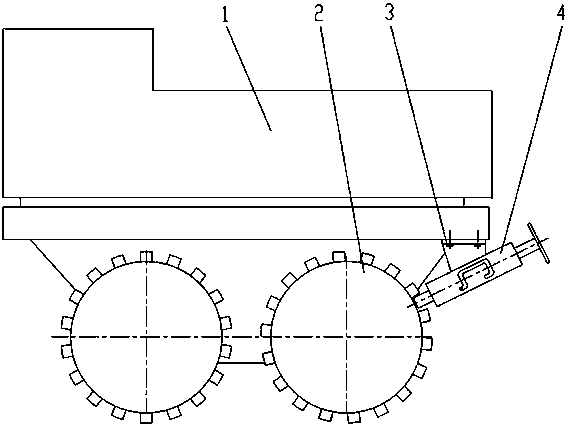
[0020] like figure 1 As shown, a road roller includes a vehicle frame 1, a lug wheel 2, a bolt 3 and a parking brake device 4, wherein the lug wheel 2 is installed on the vehicle frame 1, and the parking brake device 4 is installed on the vehicle frame through the bolt 3. On the frame 1, close to the lug wheel 2.

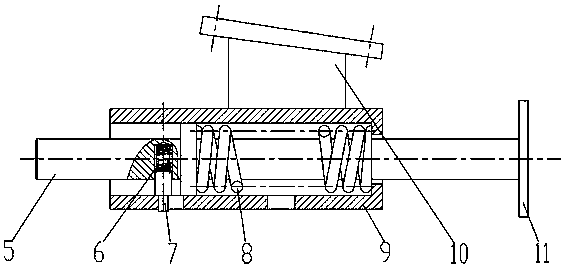
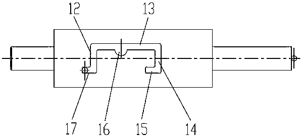
[0021] like Figure 2 to Figure 5 As shown, the parking brake device 4 includes a stop shaft 5, a cylinder liner 9 and a handle 11, wherein the stop shaft 5 is inserted in the cylinder liner 9, and a compression spring 8 is installed between the stop shaft 5 and the cylinder liner 9 , the end of the stop shaft 5 is fixedly connected to the handle 11; the stop shaft 5 is also provided with a pin hole 18 and a guide shoulder 19, and a positioning pin 7, a guide shoulder 9 and a compression spring 8 are installed in the pin hole 18 One end of the cylinder li...


PUM


Abstract

The invention discloses a parking brake device and a road roller. The parking brake device is mounted on a frame and is close to a bulge wheel of the road roller. The parking brake device is composedof a mounting base, a stopping shaft, a positioning spring, a positioning pin, retainer springs, a cylinder sleeve and a handle, wherein a guide groove is formed in the cylinder sleeve and is composedof an upper stop position, a lower stop position, a mounting groove, an upper rotating groove, a lower rotating groove and a moving groove; the upper rotating groove and the lower rotating groove communicate with the moving groove; the mounting groove is positioned on the moving groove; an axial distance exists between the upper stop position and the lower stop position; under the action of the spring force of the retainer springs, the stopping shaft can be locked on the upper stop position and the lower stop position so as to realize extension and retraction of the stopping shaft; when the stopping shaft extends to a gap between two bulges of the bulge wheel, the rotation of the bulge wheel is stopped so as to realize brake; and when the stopping shaft retracts, the brake is relieved. The parking brake device provided by the invention is simple in structure, easy to operate, reliable in brake and convenient to maintain and can avoid brake failure caused by vibration so as to improvethe safety of the road roller.

Description

technical field [0001] The invention relates to a parking brake device and a road roller using the parking brake device. Background technique [0002] Small road rollers can be divided into smooth wheel rollers and bump wheel rollers. The roller surface of the bump wheel roller has a number of regularly arranged bumps, and each bump is distributed along the circumference with gaps between them. Small bump wheel rollers are often used for compaction of foundation layers. The rollers are generally equipped with a parking brake device. Avoid accidental injury caused by the movement of the roller. [0003] In the prior art, the parking brake device of small bump wheel road rollers generally adopts wedges, that is, when the driver leaves the road roller or the road roller stops on the slope, the wedges are placed on the ground and pressed against the front and back of the wheels down to prevent the wheels from rolling. Since the wedges are inserted into the wedge frame on the ...

Claims


Application Information

Patent Timeline
Patent Type & Authority Applications(China)
IPC IPC(8): B60T1/04B60T7/10E01C19/23
CPCB60T1/04B60T7/10E01C19/23
Inventor 张静
Owner XCMG CONSTR MACHINERY
Learn More