[0021] In order to make it easy to understand the technical means, creative features, objectives and effects achieved by the present invention, the present invention will be further explained below in conjunction with specific drawings.
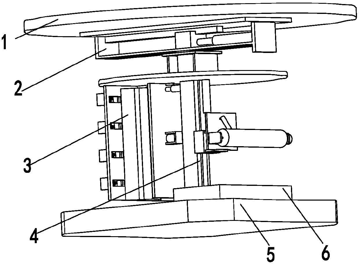
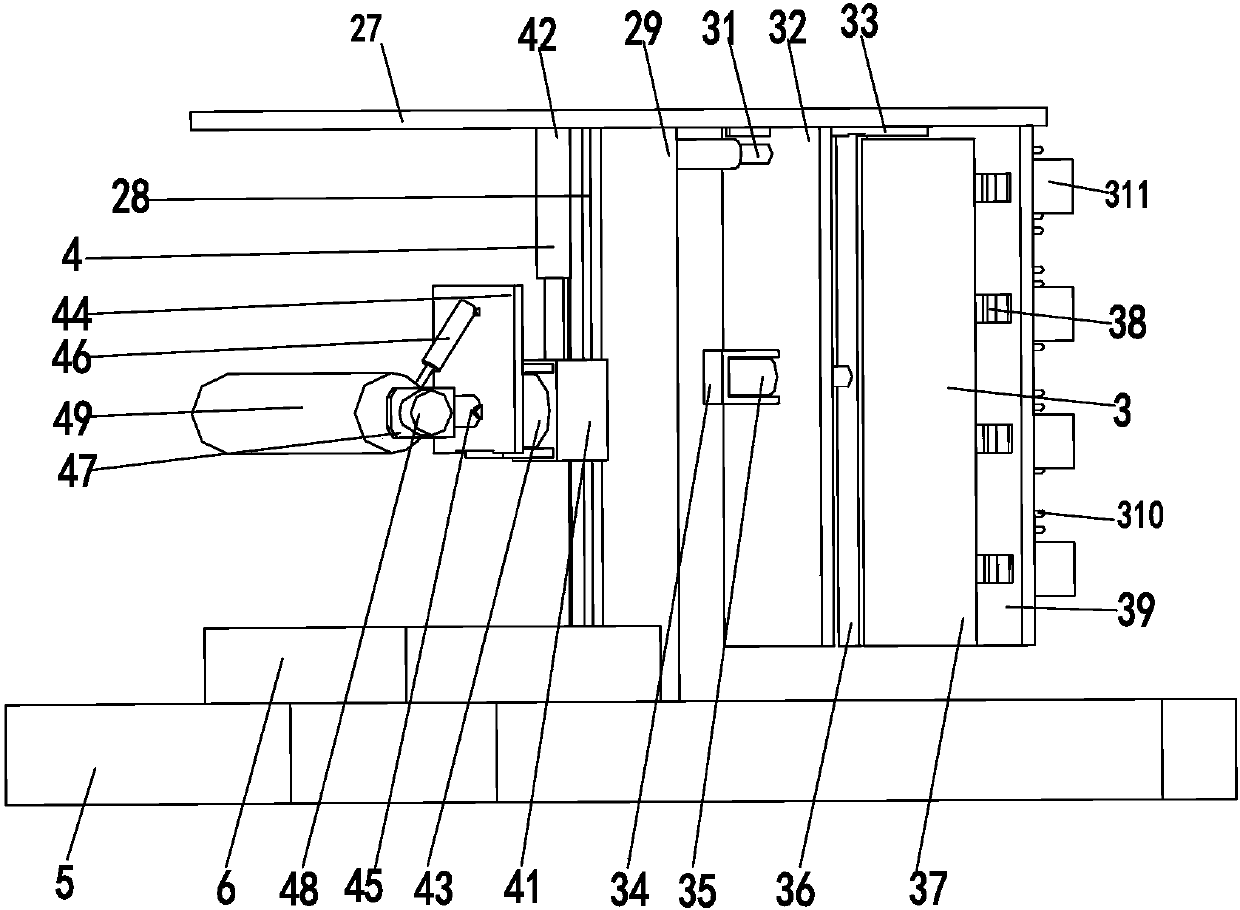
[0022] Such as Figure 1 to Figure 5 As shown, a building decoration equipment that can automatically polish and paint arc-shaped walls includes a top plate 1, an adjusting device 2, a polishing device 3, a painting device 4, a receiving tank 5 and a paint box 6. The lower end of the top plate 1 An adjusting device 2 is installed. The lower end of the adjusting device 2 is sequentially installed with a brushing device 4 and a grinding device 3 from front to back. The lower end of the grinding device 3 is equipped with a receiving tank 5. The side wall of the receiving tank 5 is an arc structure. 5 is provided with a paint box 6; among them:
[0023] The painting device 4 includes a lifting block 41, a lifting cylinder 42, a steering motor 43, a steering plate 44, a pushing cylinder 45, an adjusting hydraulic cylinder 46, a brush holder 47, a rotating motor 48 and a brush 49. The lifting block 41 is mounted on the sliding On the rail 52, the upper end of the lifting block 41 is connected with the top end of the lifting cylinder 42. The bottom end of the lifting cylinder 42 is installed at the lower end of the auxiliary mechanism 54. The front end of the lifting block 41 is installed with a steering motor 43 through the motor frame. The output shaft of the steering motor 43 passes through the motor frame. Connected to the steering plate 44, a push cylinder 45 is mounted on the side wall of the steering plate 44 through a hinge, and an adjusting hydraulic cylinder 46 is mounted on the outer wall of the push cylinder 45 through a hinge. The bottom end of the adjusting hydraulic cylinder 46 is mounted on the side wall of the steering plate 44 through a hinge. The top end of the pushing cylinder 45 is connected with the side wall of the brush holder 47. A rotating motor 48 is installed on the outer wall of the brush holder 47. The output shaft of the rotating motor 48 passes through the brush holder 47. The output shaft of the rotating motor 48 passes through the coupling and the brush 49 Connected; under the action of the lifting cylinder 42, the brush 49 is adjusted to an appropriate height, and then the position of the brush 49 is adjusted to be parallel to the ground by the rotation of the steering motor 43, and the brush 49 is driven to move by the telescopic movement of the pushing cylinder 45 To the proper position, the brush 49 is moved to the proper position by the telescopic movement of the pushing cylinder 45, and then the angle between the pushing cylinder 45 and the steering plate 44 is adjusted by adjusting the telescopic movement of the hydraulic cylinder 46, so as to dip the paint, The rotation of the steering motor 43 adjusts the position of the brush 49 to be perpendicular to the ground, and then the steering plate 44 is driven to rotate by the steering motor 43, so that the painting device 4 faces the wall to be painted, and then the telescopic movement of the pushing cylinder 45 , Push the brush 49 to contact with the wall, and then realize the painting work on the wall under the action of the rotating motor 48, without manually painting the wall, reducing the possible risk of external wall work. increase work productivity.
[0024] The adjusting device 2 includes a mounting plate 21, a sliding guide 22, a sliding block 23, a sliding frame 24, an adjusting cylinder 25, a rotating motor 26, a rotating plate 27, a connecting column 29 and a sliding rail 28. The mounting plate 21 is installed at the lower end of the top plate 1. , The lower end of the mounting plate 21 is provided with a sliding rail 22, a sliding block 23 is installed on the sliding guide 22, and a sliding frame 24 is installed at the lower end of the mounting plate 21, an adjusting cylinder 25 is installed on the inner wall of the sliding frame 24, and the top end of the adjusting cylinder 25 is installed at On the side wall of the sliding block 23, the sliding frame 24 is provided with a sliding groove, the width of the sliding groove is smaller than the maximum width of the sliding block 23, the sliding block 23 passes through the sliding groove, and the lower end of the sliding block 23 is installed with a rotating motor 26 through a motor seat. 26 The output shaft passes through the motor seat and is installed on the rotating plate 27. The lower end of the rotating plate 27 is equipped with a connecting post 29. A sliding rail 28 is provided on the front side wall of the connecting post 29. The rotating motor 26 drives the rotating plate 27 to rotate, so that the grinding The device 3 or the painting device 4 can directly face the wall, and the position of the polishing device 3 or the painting device 4 can be moved by adjusting the telescopic movement of the cylinder 25, so that the brush 49 or the arc brush 310 can touch the wall and adjust Simple and flexible, to ensure the smooth progress of follow-up work.
[0025] The polishing device 3 includes a traction cylinder 31, a moving plate 32, a moving guide rail 33, a fixing frame 34, a stretching cylinder 35, a connecting support plate 36, a tensioning plate 37, a protrusion 38, a limiting plate 39, an arc brush 310, The auxiliary plate 311 and the spring 312, the traction cylinder 31 is installed on the side wall of the connecting column 29, the top of the traction cylinder 31 is connected with the moving plate 32, the top of the moving plate 32 is connected with the moving guide 33, and the moving guide 33 is installed at the lower end of the rotating plate 27 A fixing frame 34 is installed in the middle of the moving plate 32, the inner wall of the fixing frame 34 is connected with the bottom end of the stretching cylinder 35, a through hole is provided in the middle of the moving plate 32, the stretching cylinder 35 passes through the through hole, and the top end of the stretching cylinder 35 It is connected to the connecting support plate 36. Both the left and right sides of the connecting support plate 36 are equipped with a hinged expansion plate 37. The rear end of the expansion plate 37 is evenly provided with bumps 38. The front end of the bump 38 is connected with the limiting plate 39 to limit The position plate 39 is installed on the moving guide rail 33, and the limit plate 39 is evenly provided with moving grooves. The moving grooves correspond to the positions of the protrusions 38. The protrusions 38 are installed in the moving grooves in a sliding fit. The rear end of the protrusions 38 The arc brush 310 is installed. An auxiliary plate 311 is provided on the left and right sides of the moving groove. The auxiliary plate 311 is installed on the limit plate 39, and a spring 312 is installed between the auxiliary plate 311 and the arc brush 310; The telescopic movement of 31 drives the moving plate 32 to move to the wall until the arc brush 310 can touch the wall, and then the expansion and contraction plate 37 is driven by the expansion and contraction movement of the stretching cylinder 35, so that the arc brush 310 can move The reciprocating linear movement in the groove realizes the sanding of the wall without manual sanding of the wall, which avoids the hidden safety hazards in high-altitude operations, reduces labor intensity, improves work efficiency, and the arc brush 310 can better fit the curved wall, making the polishing effect more ideal.
[0026] The paint box 6 includes a box body 61, a guide rail 62, a lifting groove 63 and a lifting electric push rod 64. The box body 61 is installed on the receiving chute 5, and the inner wall of the box body 61 is provided with a guide rail 62 for guiding A lifting groove 63 is installed on the rail 62, the lower end of the lifting groove 63 is connected with the top end of the lifting electric push rod 64, the bottom end of the lifting electric push rod 64 is installed on the inner wall of the box 61, and the width of the paint tank 6 is greater than the width of the brush 49; As the paint in the paint tank 6 continues to decrease, the height of the paint liquid level continues to drop. At this time, the height of the lifting slot 63 can be adjusted by the telescopic movement of the lifting electric push rod 64, so that the surface of the brush 49 can contact the lifting slot 63 The paint inside enables the paint in the paint box 6 to be fully utilized, avoiding the waste of paint, and the paint droplets dripping during the working process will be caught by the receiving tank 5 at the lower end of the paint box 6, and will not stain the ground. Ensure the cleanliness of the working environment.
[0027] When working, the worker places the present invention on the existing mobile equipment, and then moves the present invention to the designated working place, and the rotating motor 26 drives the rotating plate 27 to rotate until the polishing device 3 is facing the wall to be polished, and then dragged The telescopic movement of the cylinder 31 drives the moving plate 32 to move to the wall until the arc brush 310 can touch the wall, and then the expansion and hinge plate 37 is driven to expand and close by the telescopic movement of the stretch cylinder 35, so that the arc brush 310 can move The reciprocating linear movement is carried out in the groove, thereby realizing the sanding of the wall, and the dust generated by the sanding falls into the receiving groove 5 below. After the sanding work is completed, the brush 49 is adjusted to the appropriate under the action of the lifting cylinder 42 The position of the brush 49 is adjusted to be parallel to the ground through the rotation of the steering motor 43, the brush 49 is moved to a suitable position by the telescopic movement of the pushing cylinder 45, and then the pushing cylinder 45 is adjusted by adjusting the telescopic movement of the hydraulic cylinder 46. The angle between the steering plates 44 is used to dip the paint. After the angle is adjusted properly, the height of the lifting groove 63 is adjusted by the telescopic movement of the lifting electric push rod 64 so that the surface of the brush 49 can contact the lifting groove 63 The paint inside, by rotating the rotating motor 48, the surface of the brush 49 is evenly dipped in paint, and then the position of the brush 49 is adjusted to be perpendicular to the ground by the rotation of the steering motor 43, and then the steering plate 44 is driven to rotate by the steering motor 43. Make the painting device 4 face the wall to be painted, and then push the brush 49 into contact with the wall through the telescopic movement of the push cylinder 45, and then realize the painting work on the wall under the action of the rotating motor 48 The present invention solves the problems of high danger, poor cleanliness, low work efficiency, incomplete polishing and high labor intensity in the process of painting the arc-shaped wall exterior wall, and realizes the automatic polishing of the arc-shaped wall surface The function of painting has achieved the purpose.
[0028] The above shows and describes the basic principles, main features and advantages of the present invention. Those skilled in the industry should understand that the present invention is not limited by the above embodiments. The above embodiments and the description in the specification only illustrate the principles of the present invention. Without departing from the spirit and scope of the present invention, the present invention will also There are various changes and improvements, and these changes and improvements fall within the scope of the claimed invention. The scope of protection claimed by the present invention is defined by the appended claims and their equivalents.