Supercharge Your Innovation With Domain-Expert AI Agents!

Lamp capable of freely adjusting illuminating position

A free and lighting technology, which is applied to the components of lighting devices, the damage prevention measures of lighting devices, lighting devices, etc., can solve the problems of easy failure, inaccurate and inflexible adjustment displacement control, etc., and achieve accurate adjustment displacement control , Adjustment methods are diverse and flexible, and the overall structure design is simple

Pending Publication Date: 2018-03-13
广州通美科技有限公司
View PDF0 Cites 1 Cited by
  • Summary
  • Abstract
  • Description
  • Claims
  • Application Information

AI Technical Summary

Problems solved by technology

The position adjustment method of the existing lamps is often relatively single, not flexible enough, only a single horizontal displacement or vertical displacement; there are also lamps that realize both horizontal and vertical displacement functions, which are more flexible for the position adjustment of the lamps; however, the existing Lamps with one-way adjustment or multi-directional adjustment have some shortcomings, such as: the design of the adjustment structure is complicated, the adjustment operation is troublesome, the adjustment displacement control is not precise enough, the stability of the adjustment structure is not good, and it is prone to failures resulting in unsmooth adjustment, etc.

Method used


Image

  • Lamp capable of freely adjusting illuminating position
  • Lamp capable of freely adjusting illuminating position
  • Lamp capable of freely adjusting illuminating position

Examples


Embodiment Construction

[0041] The present invention will be further described below in conjunction with the accompanying drawings and specific embodiments.

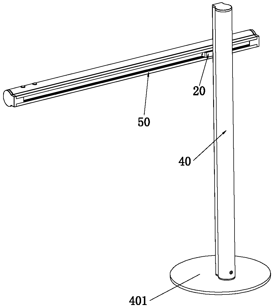
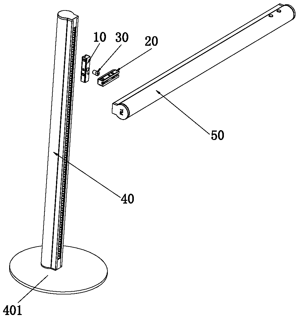
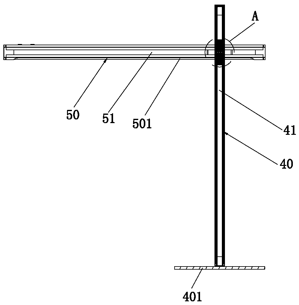
[0042] Such as Figure 1 to Figure 8 As shown, a lamp that can freely adjust the lighting position includes a first sliding mechanism 10, a second sliding mechanism 20, a rotating connector 30, a longitudinally arranged pole 40, and a laterally arranged lamp body 50, wherein:

[0043] In this embodiment, the base 401 is connected to the bottom of the pole 40, and the pole 40 extends longitudinally with a first sliding groove 41, and the aforementioned first sliding mechanism 10 can slide vertically to fit the first sliding groove. slot 41; the lamp body 50 includes a housing 501 and a light-emitting element installed in the housing 501. In this embodiment, the lampshade extends to both ends of the lamp body 50, and the end plates at both ends are designed to be relatively thin, so that the overall The effect of the light-emitting surface; the ...


PUM


Abstract

The invention relates to a lamp capable of freely adjusting an illuminating position. The lamp comprises a first slide mechanism, a second slide mechanism, a rotary connector, a supporting rod and a lamp body, wherein a first slide slot is formed in the supporting rod; the second slide mechanism can be rotatably arranged relative to the first slide mechanism through the rotary connector, so that the lamp body can be rotatably arranged relative to the supporting rod; the lamp body can be arranged in a vertical sliding mode relative to the supporting rod by enabling the first slide mechanism tomatch with the first slide slot, and the lamp body can be arranged in a transverse sliding mode relative to the supporting rod by enabling the second slide mechanism to match with the second slide slot; each of the first slide mechanism and the second slide mechanism comprises a slide mounting frame and an elastic locking assembly; and each locking blocking bump is blocked into a corresponding locking concave position or is dropped out of the corresponding locking concave position corresponding to slippage of the first slide mechanism and the second slide mechanism in the first slide slot andthe second slide slot. Therefore, the lamp is various and flexible in adjusting way, and is especially delicate and reasonable in structural design, is precise in displacement adjusting control, and is good in stability of an adjusting structure.

Description

technical field [0001] The invention relates to the field of lamps, in particular to a lamp whose lighting position can be adjusted freely. Background technique [0002] As a kind of lighting equipment commonly used in work and life, lamps and lanterns are used in various environments. The lighting height and lighting position of lamps and lanterns often need to be adjusted appropriately due to changes in work content and environment, so as to better meet Lighting needs. The position adjustment method of the existing lamps is often relatively single, not flexible enough, only a single horizontal displacement or vertical displacement; there are also lamps that realize both horizontal and vertical displacement functions, which are more flexible for the position adjustment of the lamps; however, the existing Lamps with one-way adjustment or multi-directional adjustment have some disadvantages, such as: the design of the adjustment structure is complicated, the adjustment opera...

Claims


Application Information

Patent Timeline
IPC IPC(8): F21S6/00F21V21/10F21V15/02F21V19/00F21V17/16F21V14/02
CPCF21S6/00F21V14/02F21V15/02F21V17/164F21V19/00F21V21/10
Inventor 郭先青
Owner 广州通美科技有限公司
Features
  • R&D
  • Intellectual Property
  • Life Sciences
  • Materials
  • Tech Scout
  • Unparalleled Data Quality
  • Higher Quality Content
  • 60% Fewer Hallucinations
Learn More