
Load-side energy storage optimization configuration method based on peak-shaving effect

An optimized configuration, load-side technology, applied in circuit devices, AC network load balancing, AC network circuits, etc., can solve the problems of less energy storage configuration, difficult energy storage configuration, benefit score, etc.

Active Publication Date: 2018-03-13
STATE GRID HENAN ELECTRIC POWER ELECTRIC POWER SCI RES INST +2
View PDF5 Cites 6 Cited by
  • Summary
  • Abstract
  • Description
  • Claims
  • Application Information

AI Technical Summary

Problems solved by technology

[0004] At present, there have been a lot of research results on the optimization of energy storage capacity, but most of them are on the optimization of energy storage capacity for wind farms connected to the grid, while the research on energy storage related to the load side mainly considers the integration of microgrids and photovoltaics. However, there are few studies on energy storage configuration on the load side of the power grid. In fact, there are a large number of load points in the power grid that are not connected to new energy sources and are suitable for energy storage configuration.
At the same time, in the current research on energy storage configuration on the load side of the power grid, the research methods of energy storage configuration on the load side mainly focus on calculating the peak shaving revenue according to the operation results under the strategy after formulating the output strategy. The calculated result is that the energy storage configuration is in Corresponding to the income under the control of the output strategy, it is difficult to fully represent the benefit score of the energy storage configuration

Method used


Image

  • Load-side energy storage optimization configuration method based on peak-shaving effect
  • Load-side energy storage optimization configuration method based on peak-shaving effect
  • Load-side energy storage optimization configuration method based on peak-shaving effect

Examples


Embodiment Construction

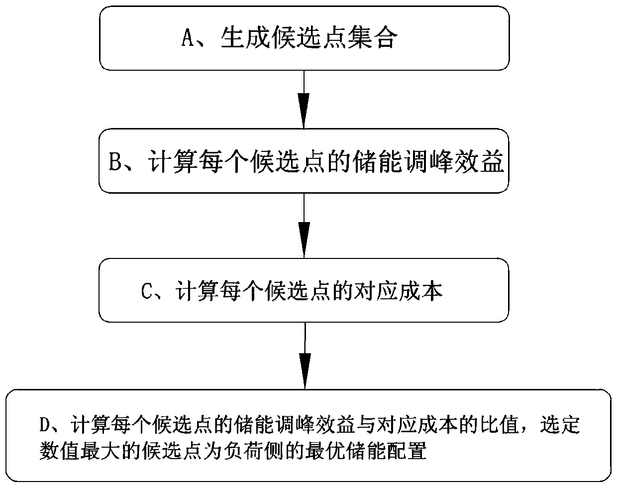
[0051] Such as figure 1 As shown, the load side energy storage configuration method described in the present invention includes the following steps:

[0052] A. Generate a set of candidate points: According to the typical daily load curve of the configuration target location, select the data points that need to be configured for energy storage as candidate points D i And constitute a set of candidate points {D 1 ,D 2 ,...,D i},D i =(P i , t i ), P i Indicates the rated power value of the i-th candidate point, t i Indicates the rated charging and discharging time value of the i-th candidate point; specifically includes the following steps:

[0053] A1. Acquisition of typical daily load data P of planned energy storage locations lo (t), where, t={1,2,3,...T}, T represents the number of data points collected in one day, typical daily load data P lo (t) exists in the form of discrete values, the typical daily load data P of different data points lo (t) constitute a typi...


PUM


Abstract

The invention discloses a load-side energy storage optimization configuration method based on a peak-shaving effect, and the method comprises the steps: firstly configuring the typical daily load dataof an energy storage load point, and generating a candidate configuration set according to the standard deviation of load data and the mean unidirectional duration; secondly taking each configurationelement in the candidate configuration set as a boundary condition, modifying the inequality constraints for calculating the peak-shaving effect, and solving the optimal value of variance of a new load curve through mixed integer programming, wherein the decrease rate of the corresponding standard deviation relative to an original curve standard deviation is taken as the benefit score of configuration; finally calculating the cost of each candidate configuration point according to power and capacity, integrating the benefit scores and the cost, such as the ratio of the decrease ratio of the standard deviation to the cost, and selecting the optimal selection from the candidate set. The method can reduce the equipment cost of power grid energy storage configuration, can quickly and accurately obtain the optimal configuration of the load-side energy storage configuration, is high in accuracy of load-side energy storage configuration, and is high in reliability.

Description

technical field [0001] The invention relates to the technical field of energy storage applications in electric power systems, in particular to a load-side energy storage optimization configuration method based on peak-shaving effects. Background technique [0002] In the energy storage configuration of the power system, for areas with large load peak-to-valley differences, with the increase of peak load, the corresponding grid equipment needs to be expanded and modified. However, in many cases, the duration of the peak load is not long, resulting in a relatively low utilization rate of power transmission channels and equipment for expansion and modification, resulting in waste of resources. [0003] Configure energy storage with a certain capacity on the load side, discharge during the peak load period to reduce the equivalent peak load of the load network, and charge during the trough period to improve the utilization rate of the corresponding grid equipment, and reduce the...

Claims


Application Information

Patent Timeline
Patent Type & Authority Applications(China)
IPC IPC(8): H02J3/32
CPCH02J3/32H02J2203/20
Inventor 石光伍俊高东学杨海晶李朝晖宋宁希张景超乔颖鲁宗相滕卫军王骅孙亮
Owner STATE GRID HENAN ELECTRIC POWER ELECTRIC POWER SCI RES INST
Learn More