Novel bridge equipment

A technology for bridges and equipment, applied in the field of new bridge equipment, can solve the problems of reduced service life, waste of power resources, damage, etc., and achieve the effects of reducing impact, saving electricity, and reducing waste

Inactive Publication Date: 2018-03-13
广州方阁建筑工程技术开发有限公司
View PDF0 Cites 0 Cited by
  • Summary
  • Abstract
  • Description
  • Claims
  • Application Information

AI Technical Summary

Problems solved by technology

[0002] Electrified maintenance equipment is often used in the bridge maintenance process. However, in some bridge constructions, there are fewer preset power supply seats and they are all fixed. This makes the power supply connection difficult. Traditionally, one or more terminal boards are used to lengthen the connection to achieve the ideal power supply connection length. However, the power supply line of the terminal board has a certain length, which is extremely inconvenient when retracting, and the power supply line is in an unused state. Exposure to the outside for a long time is easy to cause damage, and the service life is reduced; there are also many bridge power supply devices that can automatically retract and release the wires, but they need to be powered by the mains power supply to control the operation, resulting in waste of power resources

Method used


Image

  • Novel bridge equipment
  • Novel bridge equipment
  • Novel bridge equipment

Examples


Embodiment Construction

[0023] All features disclosed in this specification, or steps in all methods or processes disclosed, may be combined in any manner, except for mutually exclusive features and / or steps.

[0024] Any feature disclosed in this specification (including any appended claims, abstract and drawings), unless expressly stated otherwise, may be replaced by alternative features which are equivalent or serve a similar purpose. That is, unless expressly stated otherwise, each feature is one example only of a series of equivalent or similar features.

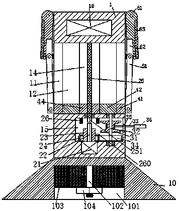
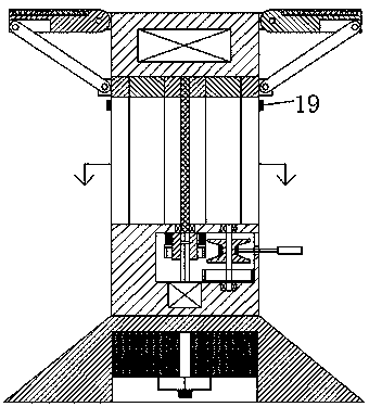
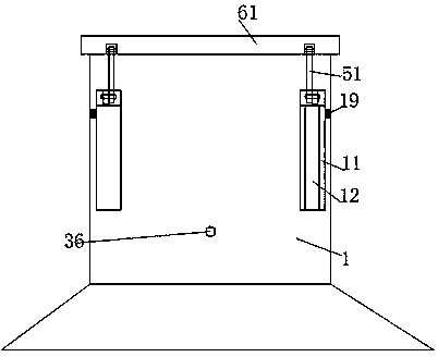
[0025] like Figure 1-5 As shown, a new type of bridge equipment of the present invention includes a power supply base 1 and a photovoltaic module, a support portion is provided under the power supply base 1 , an installation cavity 15 is provided in the bottom of the power supply base 1 , and the bottom of the installation cavity 15 A motor 21 is fixedly installed in the wall, and the top of the motor 21 is fixedly provided with a rotating m...


PUM


Abstract

Disclosed is novel bridge equipment. The novel bridge equipment comprises a power supply substrate and a photovoltaic module; a supporting part is arranged below the power supply substrate; a mountingcavity is formed in the bottom of the power supply substrate; a motor is fixedly mounted in the bottom wall of the mounting cavity; a transmission main shaft is fixedly arranged on the top of the motor; a clutch sleeve is glidingly mounted on the transmission main shaft; a driving gear is fixedly mounted on the clutch sleeve; a driven gear meshed with the driving gear is also mounted in the mounting cavity through a rotary shaft; a winding reel is also fixedly mounted on the rotary shaft; a flexible power supply line is mounted on the winding reel; the flexible power supply line passes through a through hole formed in the side wall of the mounting cavity to extend outwardly; a power supply plug board is fixedly arranged at the tail end of the flexible power supply line; the photovoltaic module comprises mounting plates which are symmetrical left and right and rotationally mounted at the upper ends of the two side walls of the power supply substrate respectively, and photovoltaic panels fixedly mounted in the mounting plates; the power supply substrate is also provided with a storage battery electrically connected with the photovoltaic panels and the flexible power supply line separately; and the power supply substrate is also provided with a driving apparatus.

Description

technical field [0001] The invention relates to the field of bridge facilities, in particular to a novel bridge equipment. Background technique [0002] Electrified maintenance equipment is often used in the bridge maintenance process. However, in some bridge constructions, there are fewer preset power supply seats and they are all fixed. This makes the power supply connection difficult. Traditionally, one or more terminal boards are used to lengthen the connection to achieve the ideal power supply connection length. However, the power supply line of the terminal board has a certain length, which is extremely inconvenient when retracting, and the power supply line is in an unused state. Exposure to the outside for a long time is easy to cause damage, and the service life is reduced; there are also many bridge power supply devices that can automatically retract and release the wires, but they need to be powered by the mains power supply to control the operation, resulting in ...

Claims


Application Information

Patent Timeline
Patent Type & Authority Applications(China)
IPC IPC(8): H02J7/35H02S20/30H01R13/72
CPCH01R13/72H02J7/35H02S20/30Y02E10/56
Inventor 欧阳翎
Owner 广州方阁建筑工程技术开发有限公司
Why Eureka
Try Eureka