
Wireless camera shooting monitoring device

A monitoring device and wireless camera technology, applied in image communication, TV, color TV components and other directions, can solve the problems of poor heat dissipation, high installation cost, single way of transmitting information, etc., to avoid high installation cost, Guaranteed not to be damaged by heat, good camera effect

Inactive Publication Date: 2018-03-13
蓝玉
View PDF0 Cites 0 Cited by
  • Summary
  • Abstract
  • Description
  • Claims
  • Application Information

AI Technical Summary

Problems solved by technology

[0002] Camera surveillance is a device that can be seen everywhere at present. With the increasing popularity of civil and commercial purposes, surveillance cameras are widely used in various fields, playing the role of escorting enterprise management and social security, and better restraint management. As the demand for camera monitoring devices continues to increase, more and more monitoring camera devices are being produced, and their functions are gradually improving. However, there are still large and small problems in the camera monitoring devices currently on the market, which plague users.
[0003] For example, there is no wireless control system, it is troublesome to transmit signals through lines, the initial installation cost is high, there is no lighting device, the camera effect is poor at night or in places with poor light, the work efficiency is not high, there is no USB interface, transmission The single way of information, poor heat dissipation, etc., lead to the failure to improve the production demand and cannot meet the demand of use

Method used


Image

  • Wireless camera shooting monitoring device
  • Wireless camera shooting monitoring device

Examples


Embodiment Construction

[0015] The technical solutions in the embodiments of the present invention will be clearly and completely described below in conjunction with the accompanying drawings in the embodiments of the present invention. Obviously, the described embodiments are only a part of the embodiments of the present invention, rather than all the embodiments. Based on the embodiments of the present invention, all other embodiments obtained by those of ordinary skill in the art without creative work shall fall within the protection scope of the present invention.

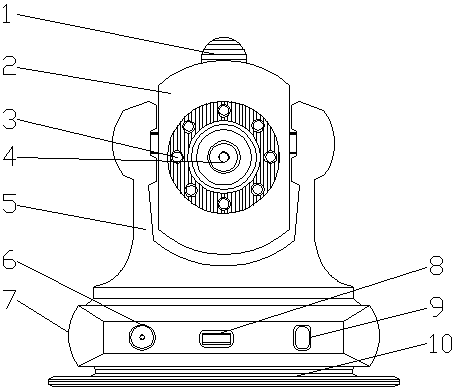
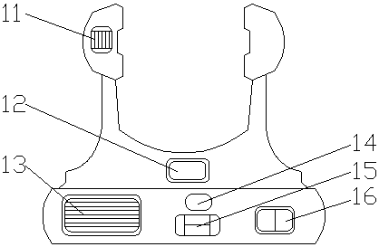
[0016] See figure 1 with figure 2 , The present invention provides a technical solution: a wireless camera monitoring device, including a signal transceiver 1, a housing 7, a fixed base 10 and an image analyzer 14. The signal transceiver 1 is connected with a protective shell 2, and the protective shell 2 rotates. The angle range is 0-180 degrees. The outer side of the protective shell 2 is equipped with a illuminating lamp 3, the middl...


PUM


Abstract

The invention discloses a wireless camera shooting monitoring device, and the device comprises a signal transceiver, a case, a fixed pedestal, and an image analyzer. The signal transceiver is connected with a protection housing, and an outer side of the protection housing is provided with an illumination lamp. A fixed frame is disposed below the protection housing, and the left side of a USB interface is fixedly provided with a power interface. The right side of the USB interface is provided with a power-on button, and the fixed pedestal is connected with the case. The interior of the case isprovided with a line box, and a signal storage box is installed below an image analyzer. The right side of the image analyzer is provided with a regulator. The device is provided with a wireless control system, is low in investment cost, is provided with an illumination lamp apparatus, is better in photographing effect, is high in work efficiency, is provided with the USB interface and the wireless signal transceiver, is large in number of information transmission modes, is good in heat dissipation effect, and guarantees the better monitoring while facilitating the application.

Description

Technical field [0001] The invention relates to the technical field of communication equipment technology, in particular to a wireless camera monitoring device. Background technique [0002] Camera surveillance is a device that can be seen everywhere. With the increasing popularity of civil and commercial use, surveillance cameras are widely used in various fields, playing a role of escort for corporate management and social security, and better restraint management. As the demand for camera monitoring devices continues to increase, more and more monitoring camera devices are produced, and their functions are gradually improving. However, the current camera monitoring devices on the market still have large and small problems that plague users. [0003] For example, there is no wireless control system, it is more troublesome to transmit signals through the line, the early installation cost is high, there is no lighting device, the camera effect is poor at night or in poor light plac...

Claims


Application Information

Patent Timeline
IPC IPC(8): H04N7/18H04N5/225H04N5/232
CPCH04N7/18H04N23/56H04N23/60
Inventor 蓝玉
Owner 蓝玉
Learn More