A method for releasing and collecting large jellyfish special for trawling
A collection method and technology of jellyfish, applied in application, fishing, animal husbandry, etc., can solve the problems of jellyfish flooding, jellyfish cannot be concentrated treatment, etc., and achieve the effect of increasing the overall length, preventing top contact, and avoiding damage
- Summary
- Abstract
- Description
- Claims
- Application Information
AI Technical Summary
Problems solved by technology
Method used
Image
Examples
Embodiment 1
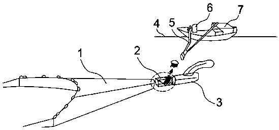
[0030] Such as figure 1 and figure 2As shown, a special large-scale jellyfish release-collection method for trawl nets is provided with a partition device 2 to separate the jellyfish at the front end of the mesh bag 3 of the trawl net 1, and the jellyfish is sucked by the fish suction tube 5 corresponding to the partition device 2, and the fish suction tube 5 is "Y "shaped pipe, filter plate can be set at the "Y" shape shunt of "Y" shape fish suction pipe 5, one pipe discharges jellyfish and a small amount of water and the other pipe discharges most of the extracted water, which is beneficial to the centralized treatment of jellyfish , and remove excess water, which is beneficial to save the work cost of jellyfish and water separation. The inlet end of the shape fish suction pipe 5 is correspondingly arranged with the partition device 2, and it is optional to arrange magnets correspondingly at the partition device 2 and the fish suction pipe 5 inlet ports or can Control the ...
Embodiment 2
[0032] refer to Figure 8 , the optimization scheme of this embodiment on the basis of Embodiment 1 is: the fish suction pump 6 includes a transmission shaft 602, the transmission shaft 602 is connected with the base 611 through a fixed frame 612, the end of the transmission shaft 602 is connected with a coupling 601, and the coupling There is a fixed bracket below the device 601, the middle part of the transmission shaft 602 is connected with a bearing, and a bearing box 603 is arranged outside the bearing, a disassembly ring 604 is connected to the top of the bearing box 603, a rear cover 605 is connected to the top of the transmission shaft 602, and the rear cover 605 A front cover plate 608 is mated and connected, an impeller 607 is arranged between the front and rear cover plates, a vortex chamber 606 is arranged at the upper and lower ends of the impeller 607, a stuffing box 609 and a water seal ring 610 are also arranged on the fixed frame 612, and a fish-absorbing ring ...
Embodiment 3
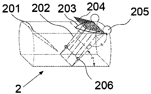
[0034] refer to Figure 2~7 , the optimization scheme of this embodiment on the basis of Embodiment 1 is: the separation device 2 is a cuboid, the separation device 2 is provided with a partition grid 202 inclined by the side of the mesh bag 3, and the two ends of the separation grid 202 are connected with floating balls 205, and the partition Grille 202 both sides are provided with collar 206, and the collar 206 of both sides is connected by the dividing grid 202 that is set horizontally, and separating grid 202 top is provided with release port 203 and closing net 204, and separating device 2 leans on trawl 1 side surface top and is inclined to set. There is an induction net 201, and the induction net 201 and the separation grid 202 form an inverted triangular space with a gap at the bottom in the separation device 2. The upper part of the separation grid 202 is bent and set, and the bending angle b is preferably 147°. The separation grid 202 and the separation device 2 are ...
PUM
 Abstract
Description
Claims
Application Information
 - R&D
- Intellectual Property
- Life Sciences
- Materials
- Tech Scout
- Unparalleled Data Quality
- Higher Quality Content
- 60% Fewer Hallucinations
Browse by: Latest US Patents, China's latest patents, Technical Efficacy Thesaurus, Application Domain, Technology Topic, Popular Technical Reports.
© 2025 PatSnap. All rights reserved.Legal|Privacy policy|Modern Slavery Act Transparency Statement|Sitemap|About US| Contact US: help@patsnap.com


