Supercharge Your Innovation With Domain-Expert AI Agents!

Indexable annular blade

A blade and ring technology, which is applied in the field of indexable ring blades, can solve the problems of reducing the cutting effect of the blade, reducing the service life of the blade, and cutting the knife, so as to achieve convenient and simple production of the knife body, improve installation reliability, and high positioning reliability Effect

Inactive Publication Date: 2018-03-16
CHENGDU TOOL RES INST
View PDF6 Cites 3 Cited by
  • Summary
  • Abstract
  • Description
  • Claims
  • Application Information

AI Technical Summary

Problems solved by technology

[0003] The axonometric diagram of the general circular blade structure is as follows figure 1 As shown, OO' is the virtual central axis of the blade, the cutting edge S is a standard ring, and X represents the arc flank of the blade. When such an blade is installed in the cutter body, due to the circular structure around There is no restriction on the axis. When the blade is in the cutting working state, the flank X and the mounting surface of the cutter body only have friction to balance the cutting force, which cannot overcome the tendency of the blade to rotate around the OO' axis, which will easily cause the blade to loosen, and then cause the knife to hit , reduce the service life of the blade and reduce the cutting effect of the blade

Method used


Image

  • Indexable annular blade
  • Indexable annular blade
  • Indexable annular blade

Examples


Embodiment 1

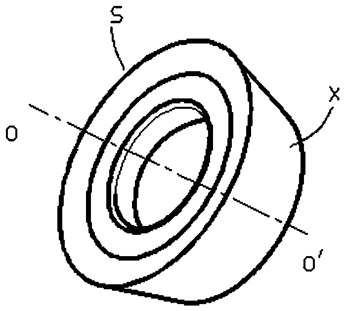
[0019] There are annular cutting edges on the upper or upper and lower sides of the indexable annular blade. The upper and lower peripheries are composed of arc lines and non-arc lines alternately. , The lower circular arc line is formed alternately by the curved surfaces of the sides.

[0020] The cutting edge projections of all the arc segments of the blade appear as different parts of the same complete circle on the plane perpendicular to the central axis of the blade, and the projections of the non-arc cutting edges appear as straight lines on the plane perpendicular to the central axis of the blade. The arc length of each arc segment is longer than the length of adjacent non-arc lines. The number of cutting edge arc segments is equal to the number of non-arc segments.

[0021] The cutting edge of the blade has several segments of circular arc and straight line, which are arranged at intervals to form a ring-shaped cutting edge; the structure of the blade flank is compose...

Embodiment 2

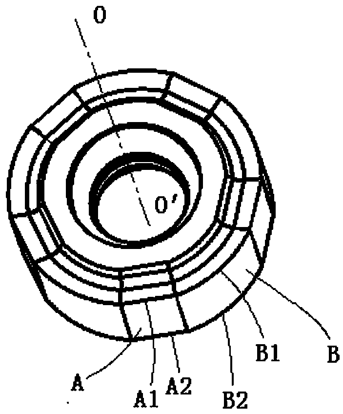
[0024] The indexable annular blade has an annular cutting edge on one side. The edge of the cutting edge and the annular blade edge are composed of arc lines and straight lines. The curved surfaces of the sides are formed alternately.

[0025] The arc length of each segment of arc is longer than that of adjacent straight lines. The number of edge arc segments is equal to the number of straight segments.

[0026] The cutting edge of this blade has several segments of circular arc and straight line, which are arranged at intervals and form an annular cutting edge; noodle.

[0027] by Figure 4 For example, a single-sided annular blade takes OO' as the axis, and has only one layer of cutting edges. B1 is the cutting edge of the circular arc segment, and the adjacent A1 is the cutting edge of the straight segment, and the arc-shaped surface of the B segment corresponds to the cutting edge segment of B1. flank of the adjacent

[0028] The plane of segment A is the flank face c...


PUM


Abstract

The invention provides an indexable annular blade. The problem is solved that an existing round indexable blade only has a cutting function, is easy to loosen, thus blade bumping is caused, the service life of the blade is shortened, and the cutting effect of the blade is reduced. The upper surface or the lower surface of the indexable annular blade is provided with an annular cutting edge, upperand lower peripheries consist of circular-arc lines and non-circular-arc lines which are alternated, and the rear blade surface of the blade is composed of a surface with upper and lower non-circular-arc line as sides and a cambered surface using the upper and lower circular-arc lines as sides in an alternated way. The blade can provide a circular-arc cutting function and can also achieve cuttingthrough the straight-line-section cutting edge. Due to the fact that the rear blade surface is provided with a flat plane, the positioning reliability during blade installation is higher than that ofa common circular blade.

Description

technical field [0001] The present invention relates to cutting tools primarily for machining operations, and in particular to indexable annular inserts. Background technique [0002] Circular indexable inserts are widely used in machining. For ordinary circular inserts, the cutting edge is generally a whole circle. [0003] The axonometric diagram of the general circular blade structure is as follows figure 1 As shown, OO' is the virtual central axis of the blade, the cutting edge S is a standard ring, and X represents the arc flank of the blade. When such an blade is installed in the cutter body, due to the circular structure around There is no restriction on the axis. When the blade is in the cutting working state, the flank X and the mounting surface of the cutter body only have friction to balance the cutting force, which cannot overcome the tendency of the blade to rotate around the OO' axis, which will easily cause the blade to loosen, and then cause the knife to hit...

Claims


Application Information

Patent Timeline
IPC IPC(8): B23B27/16
CPCB23B27/16B23B2200/0461
Inventor 涂小龙温善伦张平应显军
Owner CHENGDU TOOL RES INST
Features
  • R&D
  • Intellectual Property
  • Life Sciences
  • Materials
  • Tech Scout
  • Unparalleled Data Quality
  • Higher Quality Content
  • 60% Fewer Hallucinations
Learn More