Rotary compressor and air conditioning system

A technology for rotary compressors and air-conditioning systems, applied in the directions of compressors, compressors, rotary piston machines, etc., can solve the problems of poor working fluid flow, affecting the heat exchange efficiency of the system, and low efficiency of ordinary liquid pumps. The effect of low cost, improved system energy efficiency and high workability

Pending Publication Date: 2018-03-16
ZHUHAI LANDA COMPRESSOR +1
View PDF6 Cites 2 Cited by
  • Summary
  • Abstract
  • Description
  • Claims
  • Application Information

AI Technical Summary

Problems solved by technology

However, if no liquid pump is used, the flow effect of the working medium is not good, which affects the heat exchange efficiency of the system. The use of ordinary liquid pumps is costly, and the efficiency of ordinary liquid pumps is low, the sealing effect is not good, and the energy efficiency of the system is low.

Method used


Image

  • Rotary compressor and air conditioning system
  • Rotary compressor and air conditioning system
  • Rotary compressor and air conditioning system

Examples


Embodiment Construction

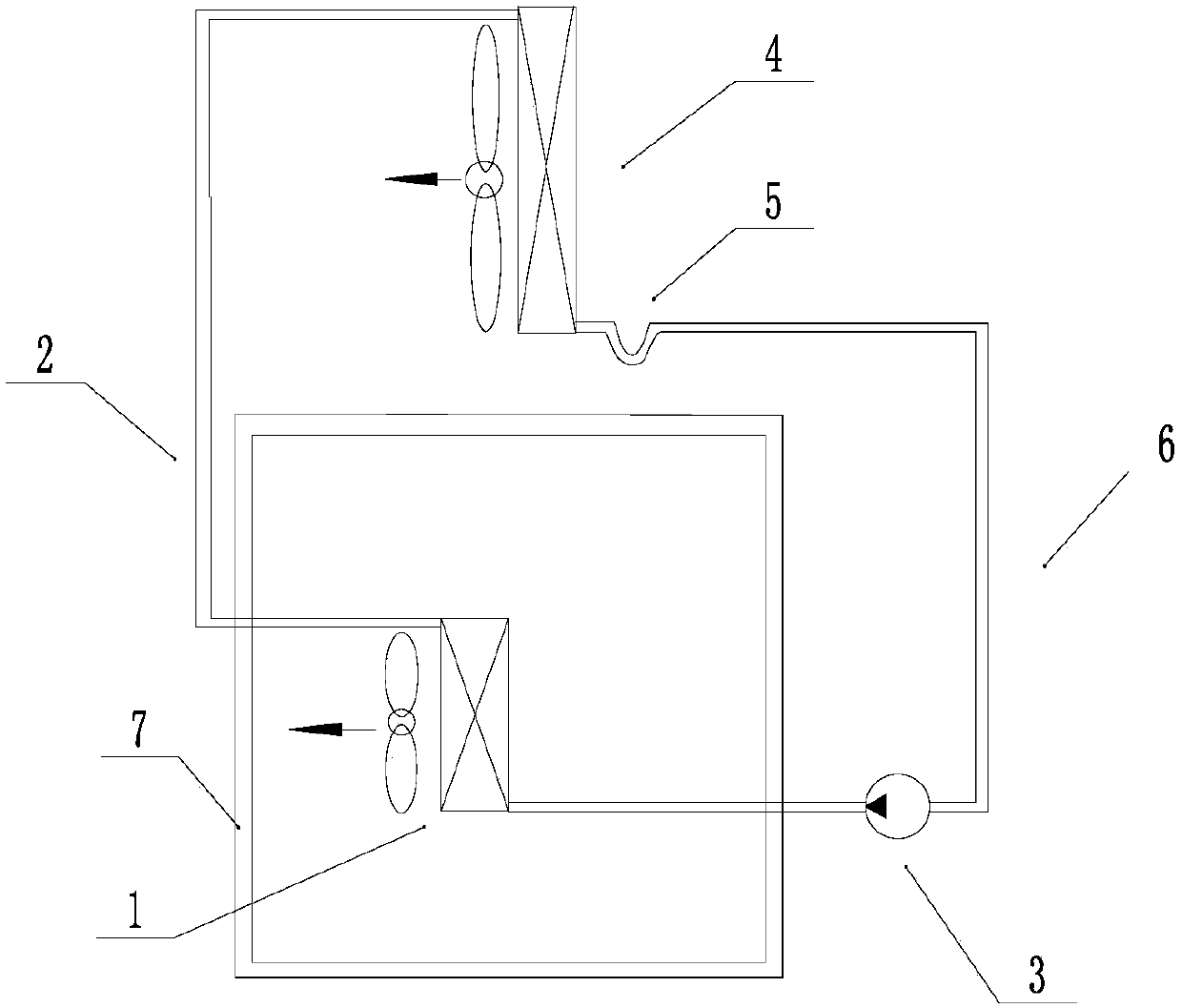
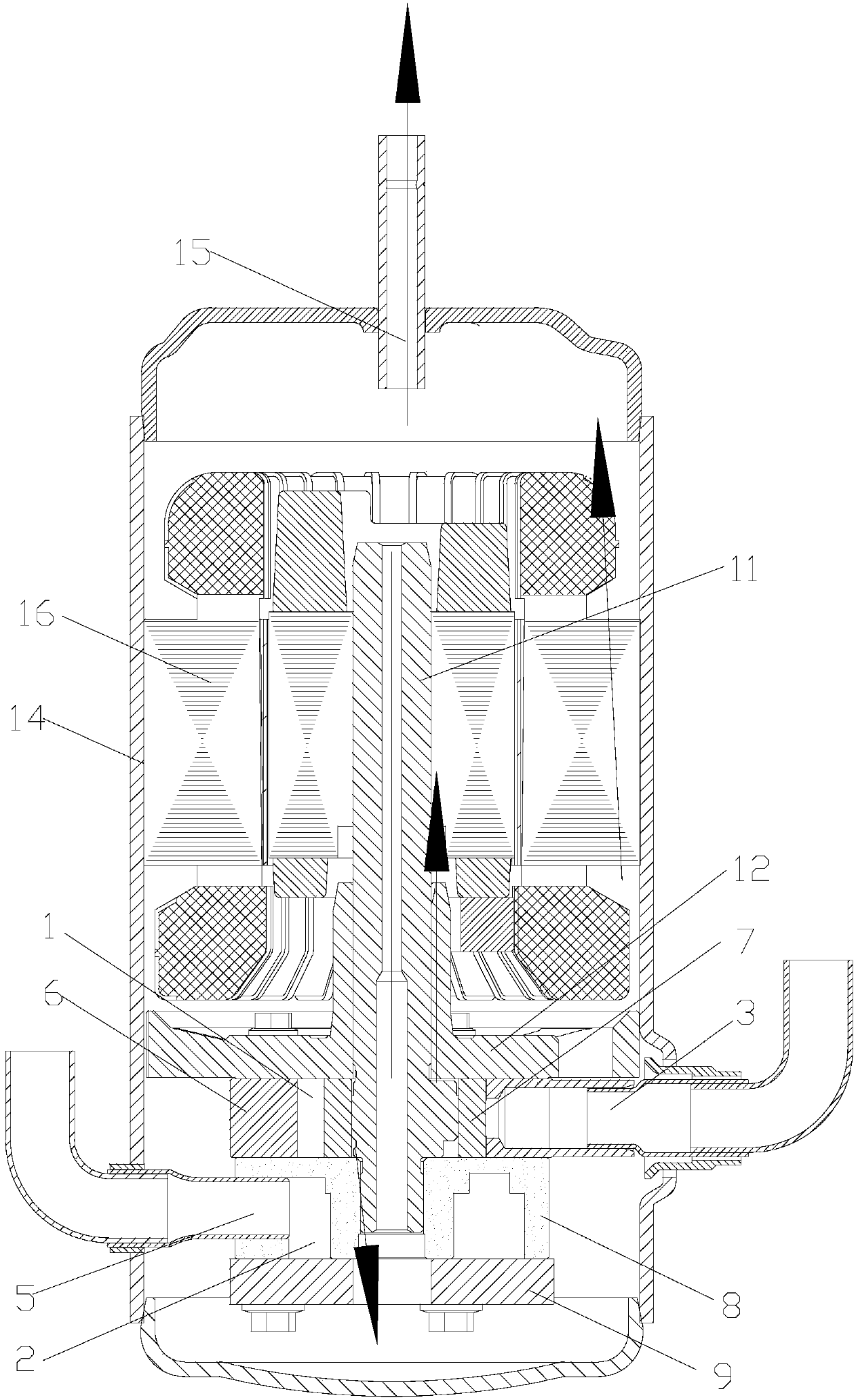
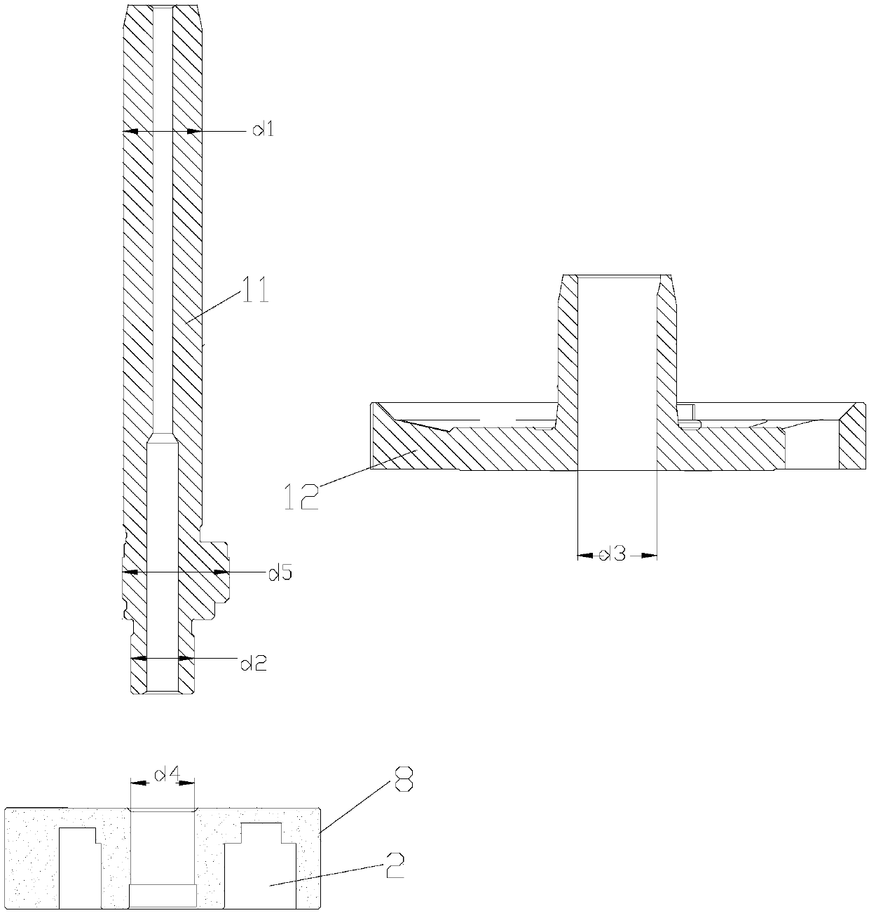
[0031] see in conjunction Figure 1 to Figure 7 As shown, according to the embodiment of the present invention, the rotary compressor includes a compression chamber 1 and a liquid discharge chamber 2, the compression chamber 1 communicates with a liquid suction port 3, and the liquid discharge chamber 2 communicates with the compression chamber 1 through a first liquid discharge port 4, The liquid discharge chamber 2 is connected with a second liquid discharge port 5 , and the liquid working medium flows from the liquid suction port 3 through the compression chamber 1 , the first liquid discharge port 4 , the liquid discharge chamber 2 and the second liquid discharge port 5 in sequence.

[0032] The rotary compressor can absorb liquid through the compression chamber and discharge liquid through the liquid discharge chamber, so it can be used instead of a liquid pump, with low cost, good sealing performance and high workability, which can effectively improve system energy effici...


PUM


Abstract

The invention provides a rotary compressor and an air conditioning system. The rotary compressor comprises a compression cavity (1) and a liquid drainage cavity (2); the compression cavity (1) communicates with a liquid suction inlet (3); the liquid drainage cavity (2) communicates with the compression cavity (1) through a first liquid drainage outlet (4) and communicates with a second liquid drainage outlet (5); and a liquid working medium flows through the compression cavity (1), the first liquid drainage outlet (4), the liquid drainage cavity (2) and the second liquid drainage outlet (5) insequence from the liquid suction inlet (3). The rotary compressor can replace a liquid pump for use, the cost is low, the working efficiency is high, and the system energy efficiency is improved effectively.

Description

technical field [0001] The invention belongs to the technical field of air conditioning, and in particular relates to a rotary compressor and an air conditioning system. Background technique [0002] Such as figure 1 As shown, it is a device for dissipating heat from a high-temperature closed environment to a large environment, and the device includes an evaporator 1, a condenser 4, a liquid collecting pipe 6, a steam pipe 2, a liquid pump 3 and a liquid storage bend 5. The condenser 4 is located on the upper part of the evaporator 1, the upper part of the evaporator 1 communicates with the condenser 4 through the steam pipe 2 and the liquid pump 3, the bottom of the evaporator 1 communicates with the bottom of the condenser 4 through the liquid collecting pipe 6 and the liquid storage bend 5, and the inside of the device A closed space is formed and filled with fluid working medium. After the evaporator 1 absorbs heat, the liquid working medium in it vaporizes, turns into...

Claims


Application Information

Patent Timeline
Patent Type & Authority Applications(China)
IPC IPC(8): F04C18/356F04C29/12F04C29/04F25B1/04F25B31/02
CPCF04C18/356F04C29/045F04C29/12F25B1/04F25B31/02F25B2400/07
Inventor 刘达炜李建宾谢利昌
Owner ZHUHAI LANDA COMPRESSOR
Why Eureka
Try Eureka