Automatic cutting device for building plate

A cutting device and building board technology, applied in the direction of shearing device, shearing machine equipment, metal processing equipment, etc., can solve the problems of poor quality of manual cutting, scattering, floor cutting and cracking, etc., so as to suppress the scattering of dust and ensure breathing safety. , The effect of improving the cutting speed

Inactive Publication Date: 2018-03-20
罗艳春
View PDF0 Cites 5 Cited by
  • Summary
  • Abstract
  • Description
  • Claims
  • Application Information

AI Technical Summary

Problems solved by technology

[0002] In the process of cutting floor and wall tiles for building decoration, it is inevitable to need to cut when laying floor and wall tiles. The common way of cutting and cutting floor and wall tiles is manual cutting. Manual cutting is flexible and convenient, but the quality of manual cutting is poor. , large dimensional error, large material waste, heavy follow-up processing workload, poor working conditions and low production efficiency
When cutting the floor manually, unskilled decoration workers often cannot cut the floor neatly into two halves, and sometimes even break the whole floor, resulting in the scrapping of the whole floor. In the process of manual cutting The cut ash layer will be scattered throughout the construction site, which will bring great harm to the respiratory health of the decoration workers. Even wearing a mask cannot prevent the human body from inhaling dust.
At the same time, the scattered ash layer will be scattered on other places on the construction site, which is not conducive to the cleaning and cleaning of the construction site, and brings a lot of inconvenience to the decoration personnel.

Method used


Image

  • Automatic cutting device for building plate
  • Automatic cutting device for building plate
  • Automatic cutting device for building plate

Examples


Embodiment

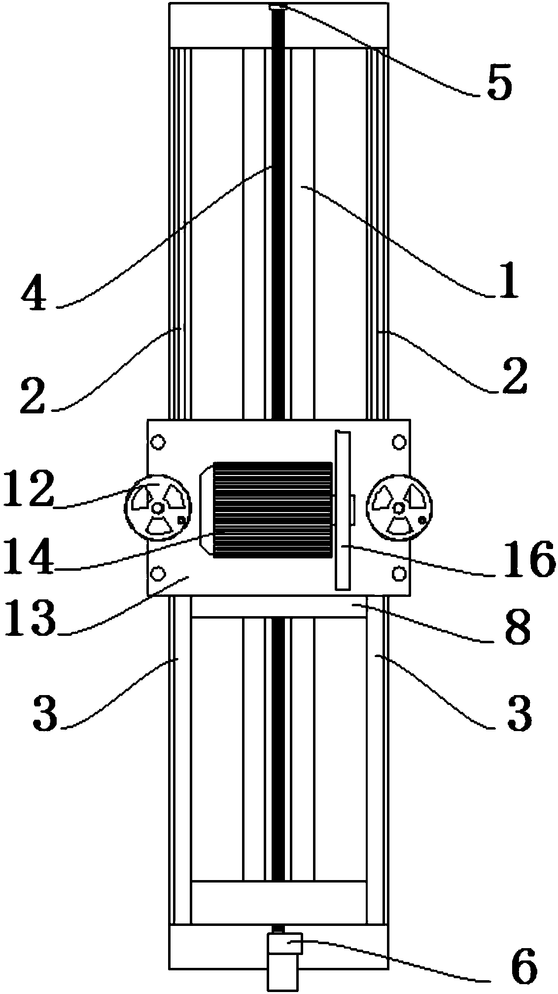
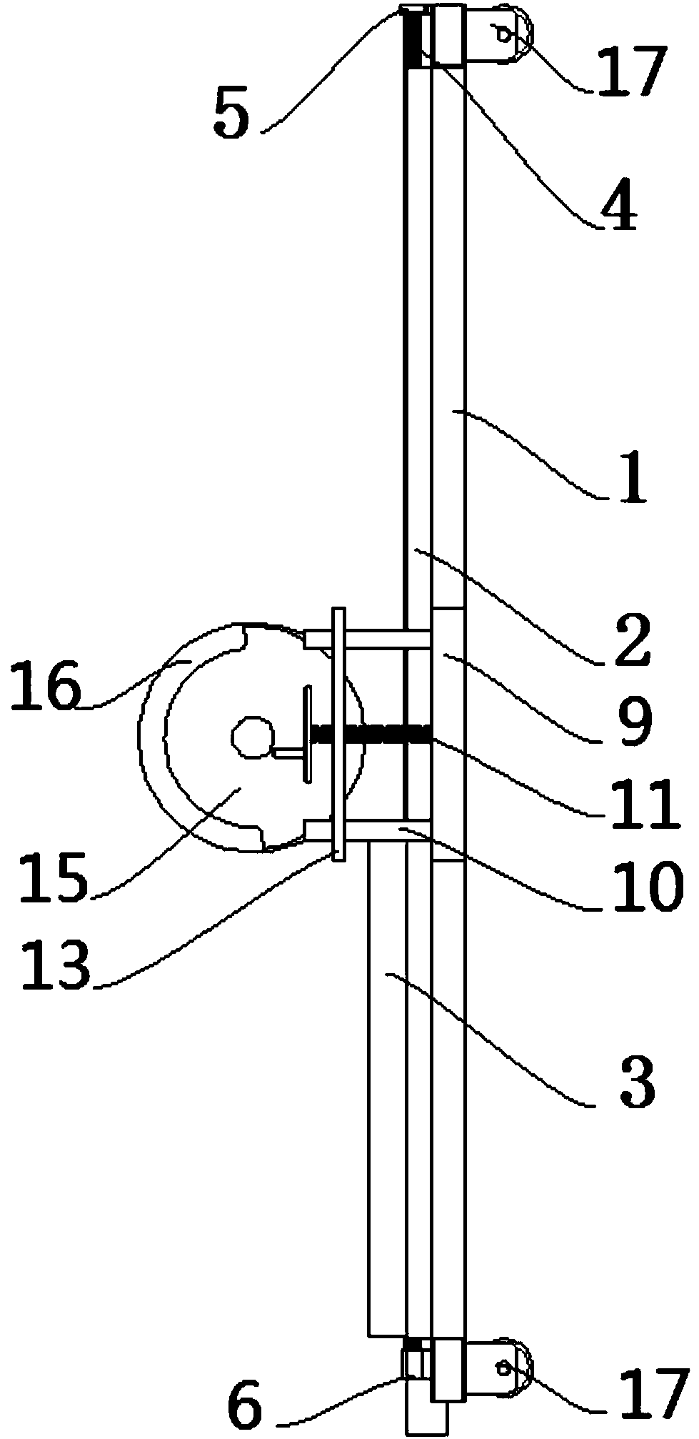
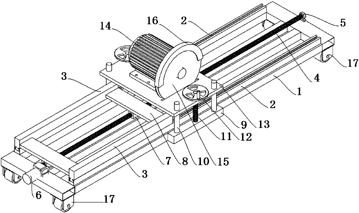
[0024] Such as Figure 1 to Figure 3 As shown, an automatic cutting device for building boards of the present invention includes a base 1 and a cutting device. Guide rails 2 are fixedly installed on the left and right sides of the base 1 respectively. The two guide rails 2 are located at the same height on the base 1. Parallel to each other, the upper ends of the guide rails 2 are matched with sliders 3 respectively, and screw rods 4 are arranged between the guide rails 2, and the screw rods 4 are parallel to the guide rails 2 respectively. One end of the screw rod 4 is fixedly connected to the base 1 through the screw bearing seat 5 , and the other end of the screw rod 4 is connected to the DC motor 6 through a shaft coupling, and the DC motor 6 is fixed on the base 1 . A screw nut 7 is matched with the screw mandrel 4, and a slider drive plate 8 is fixedly connected to the screw nut 7, and both ends of the slider drive plate 8 are respectively fixedly connected with the slid...


PUM


Abstract

The invention discloses an automatic cutting device for building boards, which comprises a base and cutting equipment. Guide rails are fixedly installed on the left and right sides of the base respectively. Slide blocks are respectively matched at the upper ends of the guide rails. Screw rods are arranged between the guide rails, and one end of the screw rod passes through The bearing seat of the screw rod is fixedly connected with the base, the other end of the screw rod is connected with the DC motor through a coupling, the DC motor is fixed on the base, the screw rod is matched with a screw nut, and the screw nut is fixedly connected with a slider drive The two ends of the drive plate and the slider drive plate are respectively fixedly connected with the slider on the guide rail. The top of the base is equipped with a cutting device. The cutting device includes a motor and a cutting blade. The cutting blade is fixedly installed on the rotor output shaft of the motor, and the motor is fixed. Installed on the motor mounting plate, the motor mounting plate is fixedly connected to the base through the motor lifting frame, and the motor mounting plate can move vertically on the motor lifting frame. The invention ensures that the incision of the building board is smooth, the cutting effect is good, and the cutting speed is improved at the same time.

Description

technical field [0001] The invention relates to the technical field of building tools, in particular to an automatic cutting device for building boards. Background technique [0002] In the process of cutting floor and wall tiles for building decoration, it is inevitable to need to cut when laying floor and wall tiles. The common way of cutting and cutting floor and wall tiles is manual cutting. Manual cutting is flexible and convenient, but the quality of manual cutting is poor. , large dimensional error, large material waste, heavy follow-up processing workload, poor working conditions and low production efficiency. When cutting the floor manually, unskilled decoration workers often cannot cut the floor neatly into two halves, and sometimes even break the whole floor, resulting in the scrapping of the whole floor. In the process of manual cutting The cut ash layer will be scattered throughout the construction site, which will bring great harm to the respiratory health of ...

Claims


Application Information

Patent Timeline
Patent Type & Authority Applications(China)
IPC IPC(8): B23D19/08
CPCB23D19/08
Inventor 罗艳春
Owner 罗艳春
Why Eureka
Try Eureka