Centrifugal compressor

A technology of centrifugal compressor and moving mechanism, which is applied in the direction of mechanical equipment, engine components, combustion engines, etc. It can solve the problems of small flow range, etc., and achieve the effect of expanding the working range, reducing suppression, and small flow resistance of suction air

Active Publication Date: 2018-03-20
MITSUBISHI HEAVY IND ENGINE & TURBOCHARGER LTD
View PDF7 Cites 1 Cited by
  • Summary
  • Abstract
  • Description
  • Claims
  • Application Information

AI Technical Summary

Problems solved by technology

[0005] However, in a conventional compressor type centrifugal compressor configured by directly sucking air into the impeller, there is a small flow range between the throttle flow rate and the surge flow rate in which stable operation can be performed, so transient changes during sudden acceleration Among them, there is a problem that in order to avoid surge, it is necessary to operate at a low efficiency operating point far from the surge flow rate.

Method used


Image

  • Centrifugal compressor
  • Centrifugal compressor
  • Centrifugal compressor

Examples


no. 1 approach

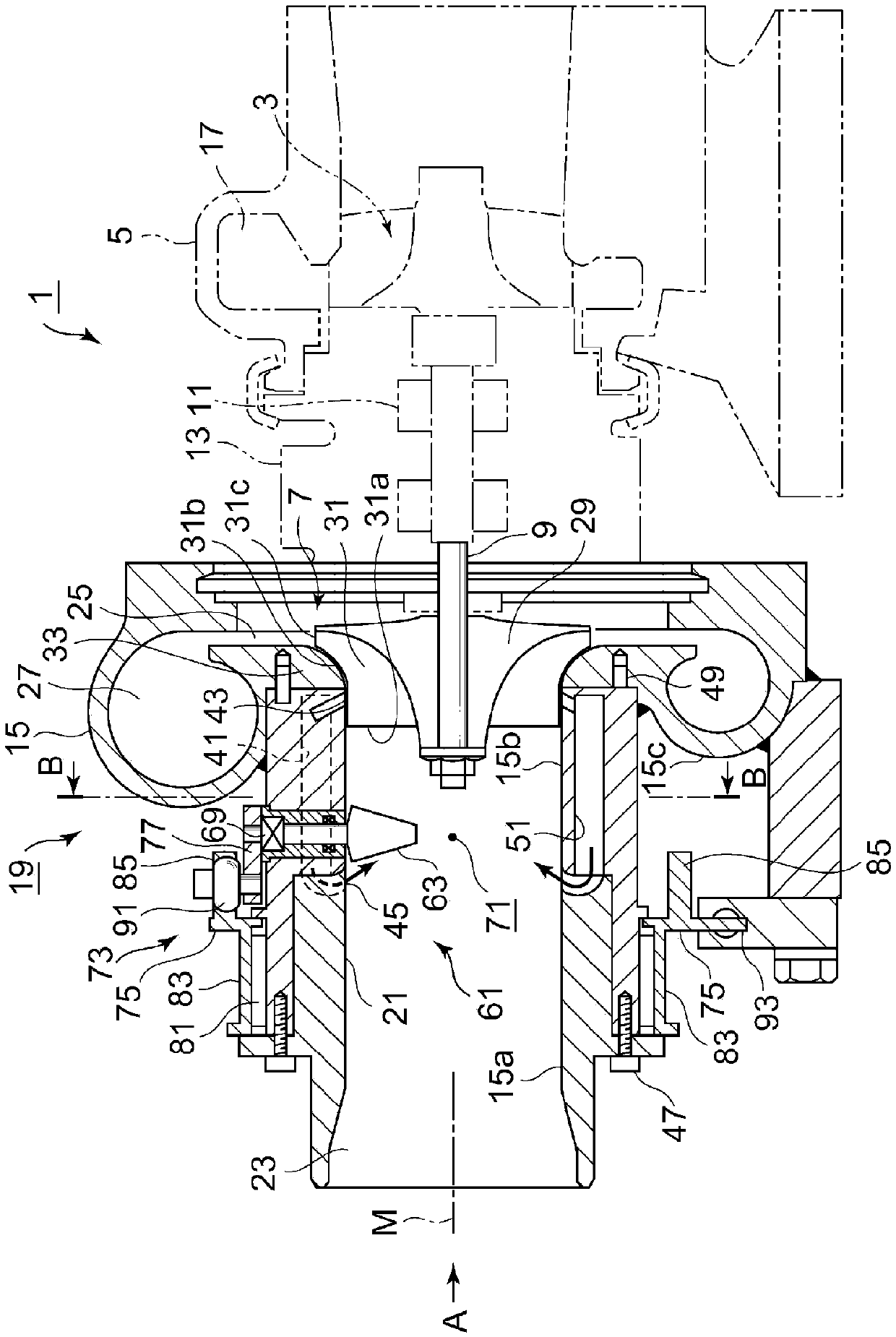
[0068] figure 1 A sectional view of main parts in the direction of the rotation axis of the exhaust gas turbocharger 1 of the internal combustion engine is shown. The exhaust turbocharger 1 is composed of a turbine housing 5, a bearing housing 13, and a compressor housing 15. The turbine housing 5 accommodates the turbine rotor 3 driven by the exhaust gas of the internal combustion engine. The bearing housing 13 The rotating shaft 9 is rotatably supported via the bearing 11, and the rotating shaft 9 transmits the rotational force of the turbine rotor 3 to the impeller 7. The compressor case 15 accommodates the impeller 7, and the impeller 7 sucks air as intake gas and performs compression.

[0069] In the outer peripheral portion of the turbine casing 5, a vortex passage 17 formed in a spiral shape is formed on the outer periphery of the turbine rotor 3, and the exhaust gas from the internal combustion engine flows from the outer peripheral side to the axial center side, and...

no. 2 approach

[0120] Next, refer to Figure 6 , to describe the second embodiment.

[0121] In the second embodiment, the recirculation channel 41 of the first embodiment is not provided, and other structures are the same as those of the first embodiment.

[0122] Such as Figure 6 In this way, the compressor housing 100 is composed of three parts: an upstream side housing 100 a , a downstream side housing 100 b , and a shroud side housing 15 c including the scroll-shaped air passage 27 . The recirculation flow path 41 is not provided in the upstream case 100a and the downstream case 100b.

[0123] In addition, the fitting surfaces of the respective members have a recessed structure to perform positioning in the direction of the rotation axis M and in the radial direction.

[0124] In addition, the guide vane 63 and the guide vane movable mechanism 73 are the same mechanisms as those of the first embodiment.

[0125] According to the above-mentioned second embodiment, as Figure 6 In t...

no. 3 approach

[0131] Next, refer to Figure 7 , to describe the third embodiment.

[0132] In the third embodiment, the shape of the inner peripheral wall of the intake flow path 21 in the first embodiment is not a cylindrical shape but a shape in which the inner diameter changes along the rotation axis M direction. Other structures are the same as those of the first embodiment.

[0133] The inner peripheral wall of the upstream casing 115a has a large diameter J, and the inner peripheral wall of the downstream casing 115b is formed so as to change from the large diameter J to the small diameter K. The small diameter K is substantially the same as the diameter of the front edge 31 a of the vane 31 of the impeller 7 .

[0134] The enlargement change from the diameter K to the major diameter J is set to expand at least an area corresponding to the area of ​​the flow path reduced by blocking the flow path with the plurality of guide vanes 63 .

[0135] That is, due to the portion of the lar...


PUM


Abstract

The invention discloses a centrifugal compressor. The centrifugal compressor aims at achieving the effects that guiding wings generating the convolute flow are located at the circumferential side, infront of a vane wheel, inside a shell, the surge limit is improved, the throttling flow is inhibited from declining, and the inclination angles of the guiding wings can be changed. The centrifugal compressor is characterized in that the centrifugal compressor is provided with a compressor body shell (15) of a compressor body (19), the vane wheel (7), the guiding wings (63), a central air suction flow channel (71) and a guiding wing movable mechanism (73); by means of the vane wheel (7), sucked air flowing therein through an air suction opening (23) is compressed; the multiple guiding wings (63) are arranged on the inner circumferential wall of an air suction channel (21) between the air suction opening (23) and the vane wheel (7) in the circumferential direction and provide the convolute flow to drive the sucked air to convolute around a rotating shaft; the central air suction flow channel (71) is formed in the inner sides of the multiple guiding wings (63), so that the sucked air fromthe air suction opening (23) flows toward the vane wheel without passing through the guiding wings (63); and by means of the guiding wing movable mechanism (73), the inclination angles of the multiple guiding wings (63) are changed in a linked manner.

Description

[0001] This application is a divisional application of the application with the application number 201280074578.0 and the title of the invention "centrifugal compressor" submitted on January 8, 2015. technical field [0002] The present invention relates to a centrifugal compressor provided with an impeller rotating by a rotating shaft, and more particularly to a centrifugal compressor incorporated in an exhaust turbocharger. Background technique [0003] In an engine used in a car, etc., in order to increase the output of the engine, an exhaust turbocharger is widely known. The exhaust turbocharger uses the energy of the exhaust gas of the engine to rotate the turbine and utilizes the The centrifugal compressor directly connected to the turbine compresses the intake air and supplies it to the engine. [0004] In the compressor of the above-mentioned exhaust turbocharger, such as Figure 10 Hysteresis occurs due to the surge flow rate (line on the left side of the graph) gen...

Claims


Application Information

Patent Timeline
Patent Type & Authority Applications(China)
IPC IPC(8): F04D17/12F04D25/02F04D27/02F04D29/46F04D29/42F02B39/04F02B37/22
CPCF02B37/225F02B39/04F04D17/12F04D25/024F04D27/0207F04D27/0246F04D29/4213F04D29/462F01D17/162F05D2250/51F05D2220/40Y02T10/12
Inventor 安秉一铃木浩
Owner MITSUBISHI HEAVY IND ENGINE & TURBOCHARGER LTD
Why Eureka
Try Eureka