Centrifugal compressor
A technology of centrifugal compressor and moving mechanism, which is applied in the direction of mechanical equipment, engine components, combustion engines, etc. It can solve the problems of small flow range, etc., and achieve the effects of expanding the working range, improving the surge limit, and reducing the flow resistance of the suction air
- Summary
- Abstract
- Description
- Claims
- Application Information
AI Technical Summary
Problems solved by technology
Method used
Image
Examples
no. 1 approach
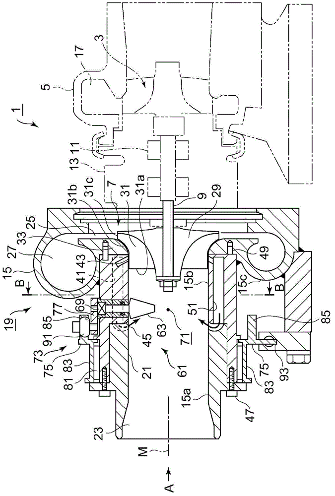
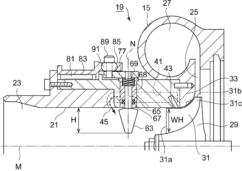
[0067] figure 1 A sectional view of main parts in the direction of the rotation axis of the exhaust gas turbocharger 1 of the internal combustion engine is shown. The exhaust turbocharger 1 is composed of a turbine housing 5, a bearing housing 13, and a compressor housing 15. The turbine housing 5 accommodates the turbine rotor 3 driven by the exhaust gas of the internal combustion engine. The bearing housing 13 The rotating shaft 9 is rotatably supported via the bearing 11, and the rotating shaft 9 transmits the rotational force of the turbine rotor 3 to the impeller 7. The compressor case 15 accommodates the impeller 7, and the impeller 7 sucks air as intake gas and performs compression.
[0068] In the outer peripheral portion of the turbine casing 5, a vortex passage 17 formed in a spiral shape is formed on the outer periphery of the turbine rotor 3, and the exhaust gas from the internal combustion engine flows from the outer peripheral side to the axial center side, and...
no. 2 approach
[0119] Next, refer to Figure 6 , to describe the second embodiment.
[0120] In the second embodiment, the recirculation channel 41 of the first embodiment is not provided, and other structures are the same as those of the first embodiment.
[0121] Such as Figure 6 In this manner, the compressor housing 100 is composed of three parts: an upstream side housing 100 a , a downstream side housing 100 b , and a shroud side housing 15 c including the scroll-shaped air passage 27 . The recirculation flow path 41 is not provided in the upstream case 100a and the downstream case 100b.
[0122] In addition, the fitting surfaces of the respective members have a recessed structure to perform positioning in the direction of the rotation axis M and in the radial direction.
[0123] In addition, the guide vane 63 and the guide vane movable mechanism 73 are the same mechanisms as those of the first embodiment.
[0124] According to the above-mentioned second embodiment, as Figure 6 I...
no. 3 approach
[0130] Next, refer to Figure 7 , to describe the third embodiment.
[0131] In the third embodiment, the shape of the inner peripheral wall of the intake flow path 21 in the first embodiment is not a cylindrical shape but a shape in which the inner diameter changes along the rotation axis M direction. Other structures are the same as those of the first embodiment.
[0132] The inner peripheral wall of the upstream casing 115a has a large diameter J, and the inner peripheral wall of the downstream casing 115b is formed so as to change from the large diameter J to the small diameter K. The small diameter K is substantially the same as the diameter of the front edge 31 a of the vane 31 of the impeller 7 .
[0133] The enlargement change from the diameter K to the major diameter J is set to expand at least an area corresponding to the area of the flow path reduced by blocking the flow path with the plurality of guide vanes 63 .
[0134] That is, due to the portion of the lar...
PUM
 Abstract
Description
Claims
Application Information
 - R&D
- Intellectual Property
- Life Sciences
- Materials
- Tech Scout
- Unparalleled Data Quality
- Higher Quality Content
- 60% Fewer Hallucinations
Browse by: Latest US Patents, China's latest patents, Technical Efficacy Thesaurus, Application Domain, Technology Topic, Popular Technical Reports.
© 2025 PatSnap. All rights reserved.Legal|Privacy policy|Modern Slavery Act Transparency Statement|Sitemap|About US| Contact US: help@patsnap.com


