Automatic coating equipment for storage battery case

A battery and shell technology, applied in the field of automatic coating equipment for battery shells, can solve the problems of low coating efficiency, poor coating effect, and inability to achieve battery shells, and achieve good coating effect, high work efficiency, and good effect. Effect

Inactive Publication Date: 2018-03-20
阜阳市金亮涂料有限公司
View PDF1 Cites 0 Cited by
  • Summary
  • Abstract
  • Description
  • Claims
  • Application Information

AI Technical Summary

Problems solved by technology

[0007] The purpose of the present invention is to address the deficiencies of the prior art, by providing an arc-shaped slide guide mechanism, and above it, a film-drawing device that can move along the arc-shaped guide-slide mechanism, through the clamping mechanism of the film-drawing device. The end is clamped to realize the rapid and automatic unfolding of the film. Cooperating with the pushing device and the rolling device and pushing device arranged at the rear end of the arc-shaped sliding mechanism to realize the automatic and rapid coating of the film on the shell and thus overcome the battery shell coating Low efficiency, inability to achieve higher automation and poor coating effect

Method used


Image

  • Automatic coating equipment for storage battery case
  • Automatic coating equipment for storage battery case
  • Automatic coating equipment for storage battery case

Examples


Embodiment 1

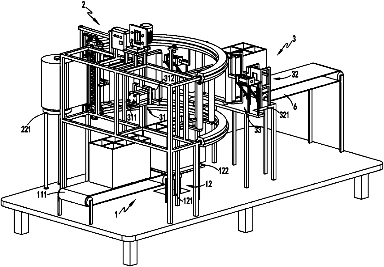
[0049] Such as figure 1 , figure 2 , image 3 , Figure 4 , Figure 5 , Image 6 , Figure 7 , Figure 8 , Figure 9 As shown, an automatic battery casing coating equipment includes a feeding part 1, and the feeding part 1 includes a horizontal conveying device 11 and a lifting device 12 arranged at the rear end of the horizontal conveying device 11;

[0050] The film pulling part 2, the film pulling part 2 is arranged on the top of the lifting device 12, the film pulling part 2 includes a guide device 21, an unwinding device 22 arranged on one side of the guide device 21 and a pulling device arranged on the guide device 21 The film device 23, the film pulling device 23 is used to pull the end of the film 10 on the unwinding device 22 to move from one end of the guide device 21 to the other end;

[0051] The coating part 3, the coating part 3 includes a pushing device 31 for pushing the shell 20 transported by the lifting device 12 to move backward to complete the coa...

Embodiment 2

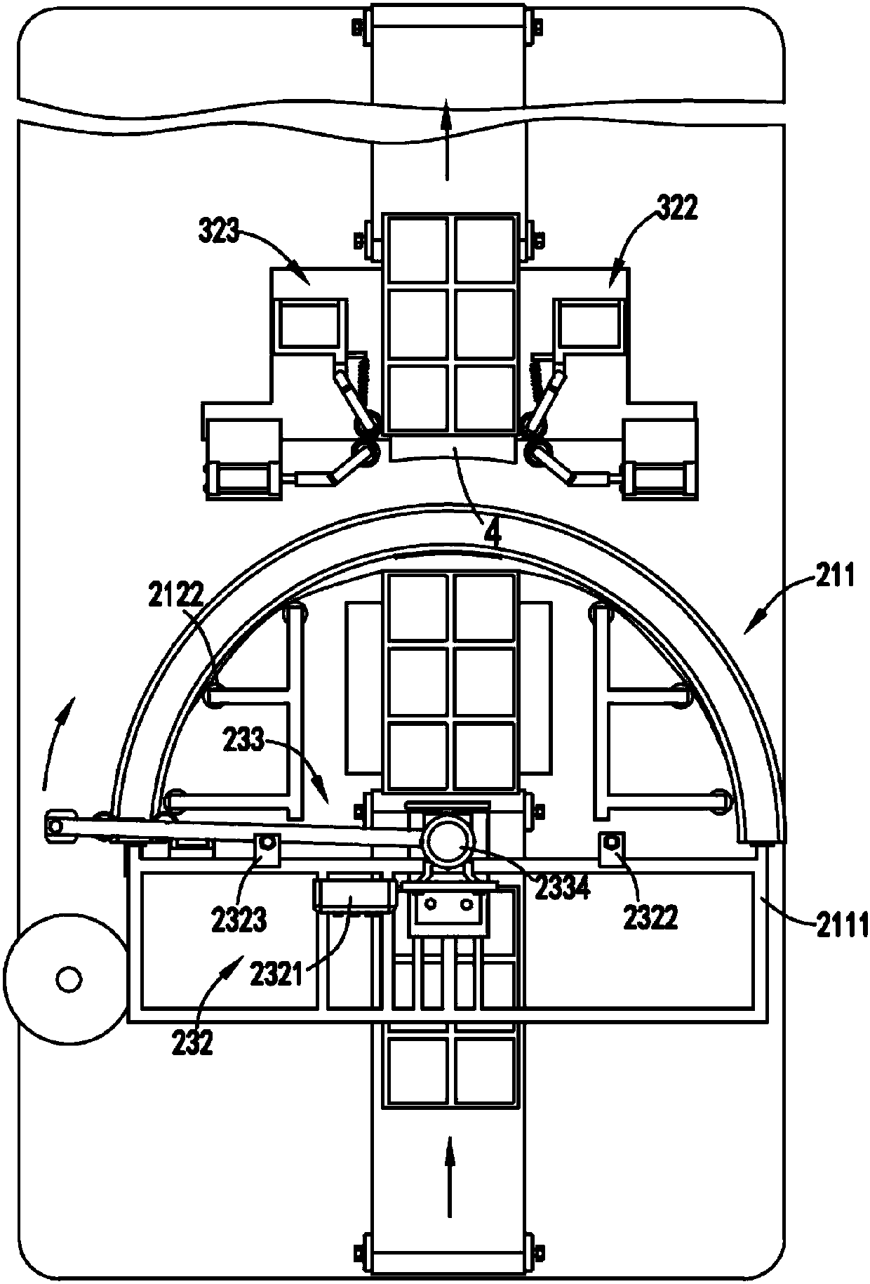
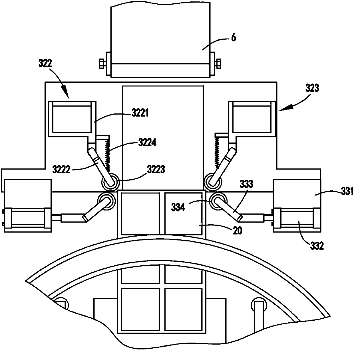
[0072] Such as figure 1 , figure 2 , image 3 , Figure 4 , Figure 5 , Image 6 , Figure 7 , Figure 8 , Figure 9 As shown, the components that are the same as or corresponding to those in the first embodiment are marked with the corresponding reference numerals in the first embodiment. For the sake of simplicity, only the differences from the first embodiment will be described below. The difference between the second embodiment and the first embodiment is that further, the pushing device 31 includes a flat-push cylinder a311 fixed on the arc-shaped guide and slide mechanism 211 and a push cylinder a311 arranged at the end of the telescopic rod of the flat-push cylinder a311. board 312;

[0073] The rolling device 32 includes a supporting base 321 and a rolling mechanism a322 and a rolling mechanism b323 symmetrically arranged on the supporting base 321. The rolling mechanism a322 and the rolling mechanism b323 both include a turret 3221, which can be rotated The ...


PUM


Abstract

The invention relates to automatic coating equipment for a storage battery case. The automatic coating equipment comprises a feeding part, a film-drawing part and a coating part, wherein the feeding part comprises a horizontal conveyor and a lifting device arranged at the rear end of the horizontal conveyor; the film-drawing part is arranged at the upper part of the lifting device and comprises aguide device, an unwinding device arranged at one side of the guide device and a film-drawing device arranged on the guide device; the film-drawing device is used for pulling the end part of a thin film on the unwinding device to move to the other end from one end of the guide device; the coating part comprises a pushing device, a rolling device and a pushing and pressing device, wherein the pushing device is used for pushing the case conveyed from the lifting device to move backwards to complete coating of the front side surface of the case; the rolling device is arranged at the rear end of the pushing device and is used for being matched with the pushing device to complete coating of two side surfaces of the case; and the pushing and pressing device is arranged at one side of the rollingdevice and is used for completing coating of the rear side surface of the case. According to the automatic coating equipment, the problems that relatively high automation cannot be achieved and the coating effect is poor due to low coating efficiency for the battery case are solved.

Description

technical field [0001] The invention relates to the technical field of film coating production equipment for lead-acid battery shells, in particular to automatic film coating equipment for battery shells. Background technique [0002] After the lead-acid battery box is processed and formed, it needs to go through the last process, that is, the surface is covered with a film to prevent the lead-acid battery box from being scratched during the subsequent transportation and assembly process. At present, some battery boxes are automatically processed on the market. Film-wrapped equipment, but the structure of the battery box conveying device is relatively complicated, the work is not reliable enough, and the cost is high. [0003] A Chinese utility model patent with the authorized announcement number CN201520374714.9 discloses a battery box conveying device of a battery box coating machine, which transfers the battery box to the coating station through a suction cup, and then pa...

Claims


Application Information

Patent Timeline
IPC IPC(8): H01M10/12H01M10/04
CPCH01M10/0404H01M10/12Y02E60/10Y02P70/50
Inventor 闫金亮沃顺财
Owner 阜阳市金亮涂料有限公司
Why Eureka
Try Eureka