Damping device for electric vacuum pump of new energy vehicle

An electric vacuum pump and shock absorber technology, applied in the direction of brake transmission, spring/shock absorber, brake, etc., can solve the problems of inability to effectively protect the electric vacuum pump, poor heat dissipation of the electric vacuum pump, and bulky structure, etc., to ensure anti-vibration effect, the effect of reducing the amplitude, improving the safety

Active Publication Date: 2022-02-08
HANGZHOU SAIQI MACHINERY CO LTD
View PDF7 Cites 0 Cited by
  • Summary
  • Abstract
  • Description
  • Claims
  • Application Information

AI Technical Summary

Problems solved by technology

[0003] Most of the damping devices used in the existing electric vacuum pumps of new energy vehicles only use a single spring damping structure to reduce the vibration amplitude of the electric vacuum pump due to the bumping of the car body. , the spring damping structure cannot effectively protect the electric vacuum pump, and because the pump body does not have a protective structure, the surface is easily damaged, and if the protective structure is installed outside the electric vacuum pump in advance, it will easily lead to poor heat dissipation and heavy structure of the electric vacuum pump

Method used


Image

  • Damping device for electric vacuum pump of new energy vehicle
  • Damping device for electric vacuum pump of new energy vehicle
  • Damping device for electric vacuum pump of new energy vehicle

Examples


Embodiment Construction

[0037] In order to make the object, technical solution and advantages of the present invention clearer, the present invention will be further described in detail below in conjunction with the accompanying drawings and embodiments. It should be understood that the specific embodiments described here are only used to explain the present invention, not to limit the present invention.

[0038] The specific implementation of the present invention will be described in detail below in conjunction with specific embodiments.

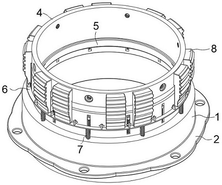
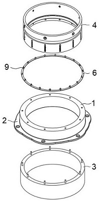
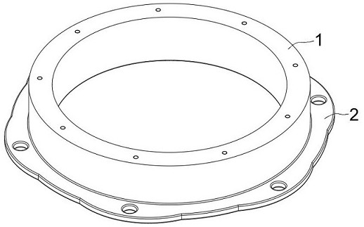
[0039] see Figure 1 to Figure 9 , a shock absorbing device for an electric vacuum pump for a new energy vehicle provided in an embodiment of the present invention, the shock absorbing device for an electric vacuum pump for a new energy vehicle includes: an annular sleeve 1 , a protective component 3 and a buffer component 4 .

[0040] In an embodiment of the invention, see figure 1, figure 2 and image 3 , the fixed sleeve on the pipe wall of the annular sl...


PUM


Abstract

The invention belongs to the technical field of new energy vehicle damping and relates to a damping device of an electric vacuum pump of a new energy vehicle. The damping device of the electric vacuum pump of the new energy vehicle comprises an annular casing pipe, a protection component and a buffer component; the pipe wall of the annular casing pipe is fixedly sleeved with a fixing flange, and a through cavity penetrating through the bottom of a pipe body is formed in the annular casing pipe; the protection component is located in the through cavity formed in the bottom of the annular casing pipe, the protection component comprises a protection pipe, the bottom of the protection pipe is fixedly embedded in the through cavity formed in the annular casing pipe, and an organ-shaped elastic air bag and a decomposing agent are installed in the protection pipe; and the buffer component is positioned on the upper pipe surface of the annular casing pipe. According to the damping device of the electric vacuum pump of the new energy vehicle, the organ-shaped elastic air bag is rapidly expanded through the internally-arranged protection component, the shell of the electric vacuum pump can be rapidly wrapped, the electric vacuum pump is effectively protected, and the problem that the shell is damaged due to collision or violent vibration of the electric vacuum pump is solved.

Description

technical field [0001] The invention relates to the technical field of shock absorption for new energy vehicles, in particular to a shock absorption device for an electric vacuum pump of a new energy vehicle. Background technique [0002] At present, the energy storage of new energy vehicles (gasoline-electric hybrid vehicles and pure electric vehicles) requires the use of high-performance power batteries. New energy vehicles are driven by electric motors, which cancel the traditional engine, so they lose the vacuum source, that is, they cannot provide vacuum for the vehicle. The brake master cylinder provides vacuum boost, and the electric vehicle vacuum booster pump is produced to make up for this deficiency. It adopts vehicle-mounted power supply to provide power, and pushes the motor on the pump body to move the piston to generate vacuum, which provides the only and reliable vacuum for hydraulic brake systems of various types of vehicles such as electric vehicles, hybrid...

Claims


Application Information

Patent Timeline
Patent Type & Authority Applications(China)
IPC IPC(8): F16F15/02F16F15/023F16F15/08A62C3/07B60T13/567
CPCF16F15/022F16F15/0232F16F15/085A62C3/07B60T13/567Y02T10/62
Inventor 刘湘桂
Owner HANGZHOU SAIQI MACHINERY CO LTD
Why Eureka
Try Eureka