Turnover positioning fixture

A technology for positioning fixtures and positioning parts, which is applied in positioning devices, clamping, manufacturing tools, etc., can solve the problems of workpiece positioning and pressing, and the workpiece is prone to movement, and achieves the effect of preventing workpiece movement and avoiding interference.

Pending Publication Date: 2018-03-23
HENAN SENYUAN ELECTRIC CO LTD
View PDF1 Cites 2 Cited by
  • Summary
  • Abstract
  • Description
  • Claims
  • Application Information

AI Technical Summary

Problems solved by technology

[0004] However, in the above-mentioned overturning fixture, when the workpiece is initially clamped, that is, when the workpiece is placed on the overturning base but the pressing mechanism is not pressed, the workpiece is in an unpositioned state. At this time, the workpiece is prone to movement, causing the pressing mechanism to The workpiece is not positioned and pressed against the set position

Method used


Image

  • Turnover positioning fixture
  • Turnover positioning fixture
  • Turnover positioning fixture

Examples


Embodiment Construction

[0033] Embodiments of the present invention will be further described below in conjunction with the accompanying drawings.

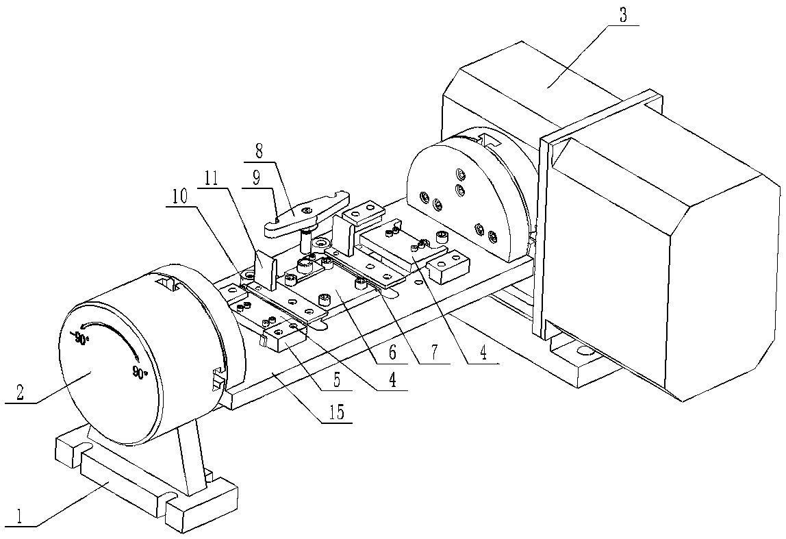
[0034] The specific embodiment of the overturn positioning fixture of the present invention, as Figure 1 to Figure 16 As shown, the present embodiment takes the processing of the workpiece 11 as an example to illustrate. It is necessary to perform drilling, chamfering and milling on the front surface of the workpiece 11, milling the front end surface and the rear end surface of the workpiece, and then by the workpiece 11. The drill holes are chamfered on the back.

[0035] The overturning positioning fixture comprises a base 1, a rotating shaft mounting seat 2 assembled on the base 1, and a rotating shaft mounting seat 2 is equipped with a turning table 15, and the turning axis of the turning workbench 15 is a horizontal axis. The overturning positioning fixture also includes a control mechanism 3 for controlling the overturning of the overturning work...


PUM


Abstract

The invention aims at providing a turnover positioning fixture in order to conduct pre-positioning on a workpiece on the premise of not affecting normal machining of the workpiece. The turnover positioning fixture comprises a base and a turnover pedestal rotatably arranged on the base around the horizontal axis. The turnover pedestal is provided with a carrying position for carrying the workpiece.The turnover pedestal is further provided with a pressing mechanism for pressing the workpiece. An end part positioning part is detachably or retractably assembled in the position, located beside thecarrying position, of the turnover pedestal. The end part positioning part is provided with a stop position used for being in stop fit with a to-be-machined surface of the workpiece so as to make thepressing mechanism to press the workpiece and is further provided with a moving position for moving the to-be-machined surface of the workpiece. Through the turnover positioning fixture, the workpiece is pre-positioned on the premise of not affecting normal machining of the workpiece.

Description

technical field [0001] The invention relates to a flip positioning fixture. Background technique [0002] In the prior art, it is sometimes necessary to mill or drill multiple surfaces of the workpiece. At this time, it is necessary to arrange the corresponding surfaces of the workpiece upwards to facilitate processing. This requires turning the workpiece multiple times to complete the processing of the workpiece. [0003] A utility model patent with the authorized notification number CN206493139U discloses a flip tooling fixture, which includes a base and a flip base mounted on the base for horizontal rotation, and a pressing mechanism for pressing the workpiece is arranged on the flip base , the pressing mechanism includes a plurality of clamping parts, the clamping part includes a hydraulic cylinder fixed on the flip base, the top of the hydraulic cylinder is fixed with a pressure head, and the hydraulic cylinder can drive the pressure head to move up and down and around ...

Claims


Application Information

Patent Timeline
IPC IPC(8): B23Q3/04
CPCB23Q3/04
Inventor 胡占楼陈小勇唐应邵赵土成乔晓辉
Owner HENAN SENYUAN ELECTRIC CO LTD
Why Eureka
Try Eureka