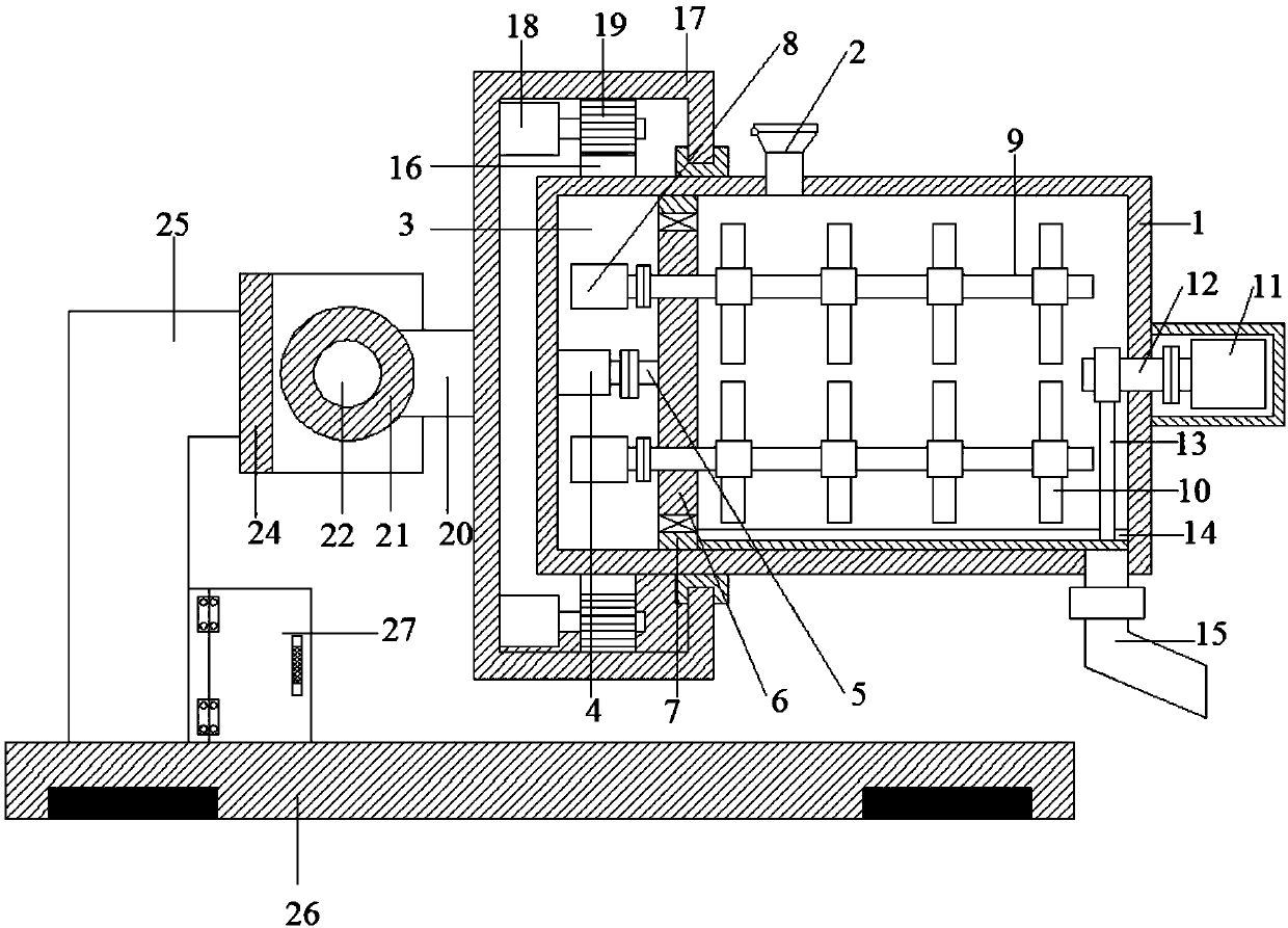
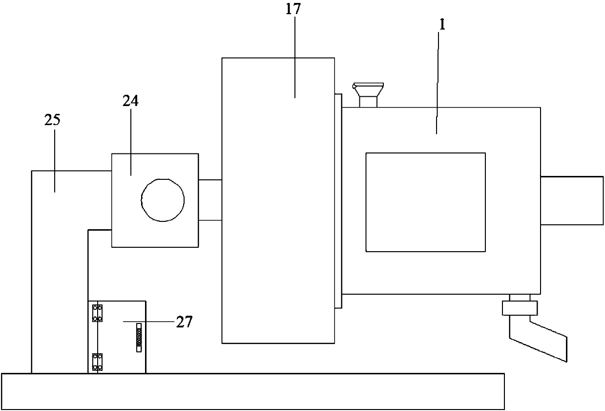
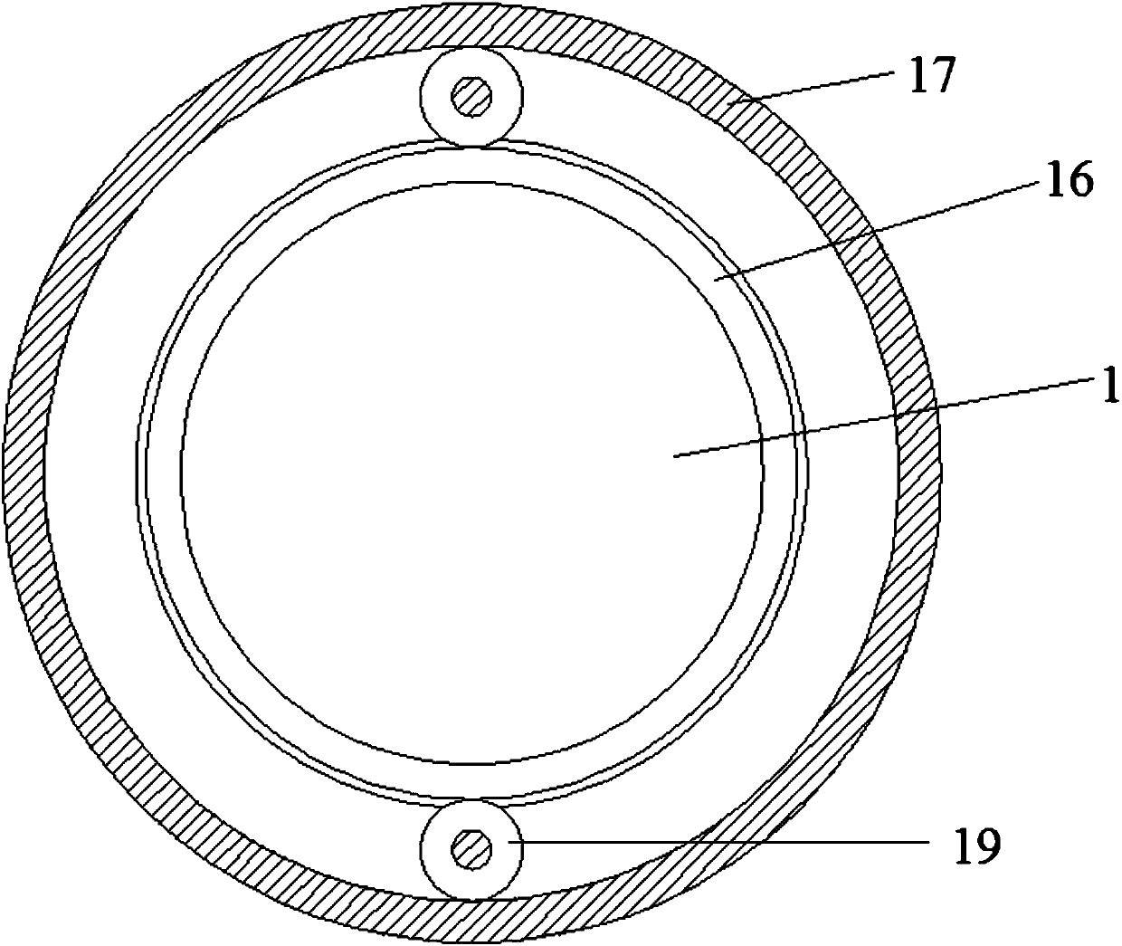
Rapid concrete stirring machine for building construction

A technology for concrete mixer and building construction, applied in cement mixing device, clay preparation device, mixing operation control and other directions, can solve the problems of affecting the service life of equipment, low mixing efficiency, inconvenient discharge of equipment, etc., to increase mixing efficiency and improve Mixing efficiency and energy saving effect

Inactive Publication Date: 2018-03-23
CHANGSHA FENGYING MACHINERY TECH CO LTD
View PDF7 Cites 8 Cited by
  • Summary
  • Abstract
  • Description
  • Claims
  • Application Information

AI Technical Summary

Problems solved by technology

[0004] We often see mixers on construction sites. The general structure of the current mixing equipment is fixed. It is fixed inside the mixing box through the stirring rod, and then the external gear is driven by the motor to rotate, so that the mixing efficienc

Method used


Image

  • Rapid concrete stirring machine for building construction
  • Rapid concrete stirring machine for building construction
  • Rapid concrete stirring machine for building construction

Examples


Embodiment Construction

[0019] It should be noted that, in the case of no conflict, the embodiments of the present invention and the features in the embodiments can be combined with each other.

[0020] In describing the present invention, it should be understood that the terms "center", "longitudinal", "transverse", "upper", "lower", "front", "rear", "left", "right", " The orientations or positional relationships indicated by "vertical", "horizontal", "top", "bottom", "inner" and "outer" are based on the orientations or positional relationships shown in the drawings, and are only for the convenience of describing the present invention and Simplified descriptions, rather than indicating or implying that the device or element referred to must have a particular orientation, be constructed and operate in a particular orientation, and thus should not be construed as limiting the invention. In addition, the terms "first", "second", etc. are used for descriptive purposes only, and should not be understood ...


PUM


Abstract

The invention discloses a rapid concrete stirring machine for building construction. The rapid concrete stirring machine for building construction comprises a stirring cavity, a seal cavity is formedin the left end in the stirring cavity, a first motor is arranged at the left end in the seal cavity, a connecting shaft is arranged on the right side of the first motor, a rotating plate is arrangedon the right side of the connecting shaft, second motors are arranged at the upper end and the lower end of the left side of the rotating plate, stirring shafts are arranged on the right sides of thesecond motors, stirring rods are arranged on the upper sides and the lower sides of the stirring shafts, a third motor is arranged on the right side of the stirring cavity, a first rotating shaft is arranged on the left side of the third motor, a first connecting rod is arranged on the lower side of the first rotating shaft, a scraping plate is arranged on the lower side of the first connecting rod, the left end of the outer side of the stirring cavity is provided with a connecting gear, a connecting cover is arranged on the outer end of the left side of a box body, a second connecting rod isarranged on the left side of the connecting cover, the left side of the second connecting rod is provided with a connecting sleeve, a connecting frame is arranged on the outer side of the connecting sleeve, an L-shaped connecting rod is arranged on the left side of the connecting frame, and a base is arranged on the lower side of the L-shaped connecting rod. According to the machine, work efficiency of the machine can be effectively improved, and discharging of the machine is facilitated.

Description

technical field [0001] The invention relates to a construction equipment, in particular to a fast concrete mixer for construction. Background technique [0002] Construction site, Cantonese called construction site, construction site, referred to as the site. A construction site is a place where construction projects are being developed and civil engineering is being carried out. Its scope is often closed by hoardings, barbed wire or walls to restrict the entry and exit of personnel, materials, machinery and vehicles. There are property management administrators guarding. You may need to register your identity and wear a helmet when entering and exiting. [0003] Design change and project visa work are very important in construction management, because of its extensive content, complicated causes, poor regularity, and long time of occurrence, it is difficult to determine its cost. Generally, the project cost adjusted due to design changes and project visas accounts for th...

Claims


Application Information

Patent Timeline
IPC IPC(8): B28C5/24B28C7/16B28C7/00B28C5/08
CPCB28C5/0868B28C5/24B28C7/00B28C7/16
Inventor 黎全
Owner CHANGSHA FENGYING MACHINERY TECH CO LTD
Why Eureka
Try Eureka