Concrete mixing device for quickly mixing concrete conveniently

A mixing device and concrete technology, which is applied to clay preparation devices, raw material supply devices for sale, cement mixing devices, etc., can solve the problems of wasting user labor and time, wasting user time and labor, and slowing down construction efficiency. , to avoid material waste, facilitate movement and fixation, and improve convenience

Inactive Publication Date: 2017-11-07
徐柳华
0 Cites 22 Cited by

AI-Extracted Technical Summary

Problems solved by technology

[0002] Concrete mixer is a machine that mixes cement, sand and gravel aggregate and water and mixes it into concrete mixture. It is mainly composed of mixing drum, feeding and unloading mechanism. The rod fully mixes cement, sand and gravel aggregates and water, so as to achieve the purpose of mixing and processing materials. The general mixers on the market fix the stirring shaft, and drive the stirring shaft to rotate through the motor, so that it is connected with the stirring shaft. The stirring rod of the mixing device moves axially to drive the mixing of ...

Abstract

The invention discloses a concrete mixing device which is convenient for rapid mixing. Motor, the bottom end of the feeding hopper is connected with the feeding port opened on the body through the feeding pipe, the material on the upper side inside the body can be discharged from the discharge port, and a second motor is arranged on the upper side of the body, the second motor The output shaft passes through the upper surface of the machine body and is fixedly connected with the first gear. The invention is a concrete mixing device convenient for rapid mixing, which can pre-crumble the materials, and the stirring shaft revolves around the body axis while rotating. It can fully mix the internal materials, and scrape off the materials adhered to the inner wall of the machine. During the mixing process, it can drive the machine body to shake left and right, further improving the mixing efficiency, and can effectively avoid the generation of air bubbles. In addition, it can be conveniently It can be fixed and moved with high convenience.

Application Domain

Cement mixing apparatusSold ingredients supply apparatus

Technology Topic

Image

  • Concrete mixing device for quickly mixing concrete conveniently
  • Concrete mixing device for quickly mixing concrete conveniently
  • Concrete mixing device for quickly mixing concrete conveniently

Examples

  • Experimental program(1)

Example Embodiment

[0019] The technical solutions in the embodiments of the present invention will be clearly and completely described below in conjunction with the accompanying drawings in the embodiments of the present invention. Obviously, the described embodiments are only a part of the embodiments of the present invention, rather than all the embodiments. Based on the embodiments of the present invention, all other embodiments obtained by those of ordinary skill in the art without creative work shall fall within the protection scope of the present invention.
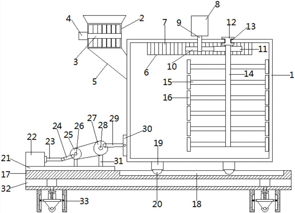
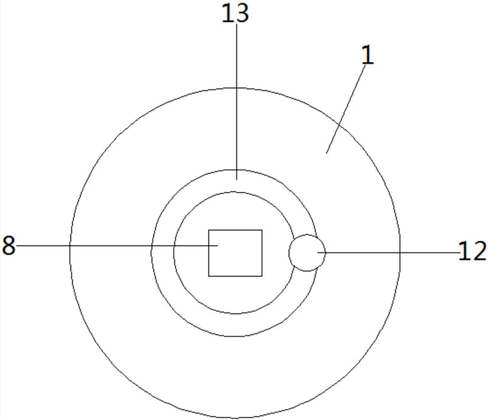
[0020] See Figure 1-2 In the embodiment of the present invention, a concrete mixing device that facilitates rapid mixing includes a body 1, a feed hopper 2 is provided at the upper left end of the 1 and a pre-crushing mechanism 3 is horizontally provided inside the feed hopper 2. The pre-crushing mechanism 3 includes a horizontally arranged pre-crushing shaft and a pre-crushing blade arranged on the outer wall of the pre-crushing shaft. The left end of the pre-crushing mechanism 3 is connected with a first motor 4, and the bottom end of the hopper 2 is connected to The feed port opened on the body 1 is connected, and a second motor 8 is provided on the upper side of the body 1. The second motor 8 is a servo motor. The output shaft of the second motor 8 passes through the upper surface of the body 1 and is fixedly connected with For the first gear 10, a circular ring 6 is fixedly connected to the top center of the inner wall of the body 1. The inner wall of the circular ring 6 is provided with a rack 7; the upper surface of the body 1 is provided with an annular through hole 13, and the annular through hole 13 is clamped The slider 12, the shape of the slider 12 is a cylinder and the surface of the slider 12 is provided with a full circle of grooves matching the annular through hole 13, and the center of the lower surface of the slider 12 is fixedly connected with a stirring shaft 14 for stirring The surface of the shaft 14 is fixedly connected with a second gear 11 which meshes with the first gear 10 and the rack 7 respectively. The surface of the stirring shaft 14 is fixedly connected with a main stirring rod 15, and both ends of the main stirring rod 15 are fixed. The auxiliary stirring rods 16 arranged vertically are connected, the number of the main stirring rods 15 is at least six, and the five main stirring rods 15 are equidistantly arranged on the surface of the stirring shaft 14 from top to bottom. The rod 16 is in the shape of a thin plate and the end of the auxiliary stirring rod 16 is attached to the inner wall of the body 1. When the device is working, the pre-crushing mechanism is set up to effectively pre-crush the materials entering the body to smash and refine the materials. It can effectively improve the subsequent mixing efficiency. Through the operation of the second motor 8, the first gear 10 is driven to rotate, and the second gear 11 meshed with it is driven to rotate. The second gear 11 rotates, so that the second gear 11 moves along the rack 7 , By setting the main stirring rod and the auxiliary stirring rod, when the stirring shaft rotates, the main stirring rod and the auxiliary stirring rod are driven to fully stir the material. By setting the second motor, the first gear, the rack, the sliding block and the stirring shaft, When the servo motor is operating, the first gear is linked to the second gear, so that the second gear rotates around the first gear, so that the stirring shaft rotates around the first gear while rotating itself, so that the stirring rod is carried out in the stirring tank. Irregular movement greatly improves the mixing efficiency and makes the mixing more complete. At the same time, the materials attached to the wall of the mixing tank can be scraped off to avoid material waste and facilitate later cleaning.
[0021] See figure 1 In the embodiment of the present invention, a base 17 is provided on the lower side of the body 1, and a sliding groove 18 is provided on the base 17, and a supporting leg 19 is provided around the lower side of the body 1. Both ends are provided with balls 20, a backing plate 21 is fixedly connected to the left side of the top of the base 1, a cylinder 22 is fixedly connected to the top of the backing plate 21, and a first connecting rod 23 is fixedly connected to the output end of the cylinder 22. A second connecting rod 24 is movably connected to the right side of the second connecting rod 24, a first turntable 25 is movably connected to the right side of the second connecting rod 24, and a first rotating shaft 26 is fixedly connected to the axis of the first turntable 25. The surface is connected with a second turntable 27 through a transmission belt. The second turntable 27 is fixedly connected to the second turntable 28 at its axis. The first turntable 26 and the second turntable 28 are away from the surface on the side of the first turntable 25 and the second turntable 27 The column 31 is movably connected. The bottom of the column 31 is fixedly connected to the top of the backing plate 21. The right side of the front surface of the second turntable 27 is movably connected to a connecting column 29. The right side of the connecting column 29 is slidably connected to a sliding plate 30. The right side of 30 is fixed on the left outer wall of the body 1. During the mixing process, the movement of the air cylinder drives the movement of the first connecting rod, so that the movement of the first connecting rod drives the first turntable to rotate through the second connecting rod. A turntable drives the second turntable through the transmission belt, and the rotation of the second turntable drives the connecting column to move, so that the movement of the connecting column drives the sliding plate to move left and right, so that the body shakes left and right during the mixing process, further improving the mixing device The mixing efficiency can also effectively avoid the generation of bubbles during mixing.
[0022] See figure 1 with image 3 In the embodiment of the present invention, the base 17 is provided with empty slots 32 inside, and the four lower corners of the base 17 are provided with mobile support devices 33. The mobile support devices 33 include hollow columns 332 fixed at the four corners of the bottom of the base 17. And the third motor 331 fixed inside the cavity 32, the output shaft of the third motor 331 penetrates to the cavity of the hollow column 332 and is fixedly connected with the screw 333, the surface of the screw 333 is engaged with a screw block 334, and the bottom of the screw block 334 is fixed A support plate 336 is connected. Both sides of the support plate 336 are fixedly connected with a sliding plate 335. The side of the sliding plate 335 away from the support plate 336 is fixedly connected with a sliding block 337. The inner wall of the hollow column 332 is provided with the sliding block 337. The bottom of the support plate 336 is fixedly connected with a support frame 339, and the bottom of the support frame 339 is movably connected with a roller 3310. When the device needs to move, the third motor 331 is controlled to run, so that the third motor 331 drives the screw 333 Rotation, the screw block 334 is moved by the rotation of the screw 333, the support plate 336 is driven by the movement of the screw block 334, and the support frame 339 and the roller 3310 are extended to the bottom of the hollow column 332 by the movement of the support plate 336. For the effect of movement, when fixing is required, the roller 3310 can be moved up to the inside of the hollow column, which can be moved and fixed conveniently, which improves the convenience of the device.
[0023] The working principle of the present invention is: by setting the main stirring rod and the auxiliary stirring rod, when the stirring shaft is rotated, the main stirring rod and the auxiliary stirring rod are driven to fully stir the material, and the second motor, the first gear, the rack, The slider and the stirring shaft. When the servo motor is operating, the first gear is linked to the second gear to make the second gear rotate around the first gear, so that the stirring shaft rotates around the first gear while rotating, so as to stir The rod moves irregularly in the mixing tank.
[0024] For those skilled in the art, it is obvious that the present invention is not limited to the details of the above exemplary embodiments, and the present invention can be implemented in other specific forms without departing from the spirit or basic characteristics of the present invention. Therefore, from any point of view, the embodiments should be regarded as exemplary and non-limiting. The scope of the present invention is defined by the appended claims rather than the above description, and therefore it is intended to fall within the claims. All changes within the meaning and scope of equivalent elements of are included in the present invention. Any reference signs in the claims should not be regarded as limiting the claims involved.
[0025] In addition, it should be understood that although this specification is described in accordance with the implementation manners, not each implementation manner only includes an independent technical solution. This narration in the specification is only for clarity, and those skilled in the art should consider the specification as a whole The technical solutions in each embodiment can also be appropriately combined to form other implementations that can be understood by those skilled in the art.

PUM

no PUM

Description & Claims & Application Information

We can also present the details of the Description, Claims and Application information to help users get a comprehensive understanding of the technical details of the patent, such as background art, summary of invention, brief description of drawings, description of embodiments, and other original content. On the other hand, users can also determine the specific scope of protection of the technology through the list of claims; as well as understand the changes in the life cycle of the technology with the presentation of the patent timeline. Login to view more.

Similar technology patents

Stirring machine for food processing

InactiveCN111135738AIncrease circulation velocityImprove stirring efficiencyFlow mixersTransportation and packagingProcess engineeringBLENDER/MIXER
Owner:SHANDONG JIASHIBO FOOD

Classification and recommendation of technical efficacy words

  • Improve stirring efficiency
  • Stir well

Pipe flow type inner wall erosion corrosion test device

InactiveCN103335939AImprove stirring efficiencyImproved media uniformityWeather/light/corrosion resistanceAuxiliary electrodeTangential force
Owner:INST OF METAL RESEARCH - CHINESE ACAD OF SCI

Chemical raw material stirring and drying device

Owner:长沙德科投资管理咨询有限公司

Magnetic power stirring machine

Owner:ZHONGSHAN CITY GOLDLABO ELECTRIC CO LTD
Why Eureka
Try Eureka