Reaction cell and operation method thereof

a technology of reaction cell and operation method, which is applied in the field of reaction cell, can solve the problems of large amount that is counter to reducing the cost of analysis and production, difficult to apply the vibration means to the reaction cell that has been made smaller, and internal solution is likely to stagnate or come into a laminar flow, so as to promote uniform agitation, promote the effect of reaction promotion, and increase the degree of freedom of controlling the reaction

Inactive Publication Date: 2008-03-11
NGK INSULATORS LTD
View PDF30 Cites 21 Cited by
  • Summary
  • Abstract
  • Description
  • Claims
  • Application Information

AI Technical Summary

Benefits of technology

[0009]The present invention has been made in view of the above-described problems and an object thereof is to provide a reaction cell which can be made small in size and which can enhance the agitation efficiency and realize the control of the reaction, and a method of using that reaction cell.
[0017]In place of zirconia, the cell may be made from optical transmissive ceramics. In a case where using the optical transmissive ceramics, the status of reaction of the solution can be detected by light. Also, the cell may be made into a hybrid structure wherein the circumferential wall portion is formed using ceramics and the bottom portion is formed using transparent glass or synthetic resin. Further, the cell may also be made into a structure wherein the circumferential wall portion and bottom portion are formed using transparent glass or synthetic resin and the piezoelectric / electrostrictive oscillator is adhered onto the circumferential wall or bottom portion. By having the cell integrally sintered with optical transmissive ceramics, the piezoelectric / electrostrictive oscillator can be sintered and formed directly on the cell. Also, by having the cell made up into a structure wherein the circumferential wall portion is made of ceramics and the bottom portion is made of transparent glass or synthetic resin, the following merits are obtained. Namely, peripheral portions of the cell can stably be produced employing a manufacturing method that is suitable for mass-production, such as green sheet lamination, sintering, etc. In addition, a combined structure with the transparent glass or synthetic resin as the bottom portion which is suitable for immobilizing biopolymer, etc. and detecting the status of the reaction through the use of a light can be realized. This enables providing a reaction cell that is inexpensive and has high performance. Also, by having the cell made up into a structure wherein the piezoelectric / electrostrictive oscillator is adhered onto the circumferential wall portion or the bottom portion, more options about a selection of the material applied to the circumferential wall portion or bottom portion are given. As a result, optimum selection of the material becomes possible from the biochemical point of view.

Problems solved by technology

In addition, using expensive material such as a DNA sample, reagent, enzyme, etc. in large amount runs counter to reducing the cost for analysis and production.
On the other hand, vibration means such as the above-described vibrator and ultrasonic oscillator has the difficulty of reducing the size thereof and, therefore, it is also difficult to apply that vibration means to the reaction cell that has been made smaller in size or finer in structure.
Also, even if using the above-described vibrator or ultrasonic oscillator for agitating the solution within the reaction cell, the internal solution becomes likely to get stagnated or come into a laminar flow.
Especially, in a case where the amount of the solution is small and the viscosity of the solution is relatively high, effective agitation becomes further difficult to perform.
Further, in a case where the vibrator or the ultrasonic oscillator is employed, there is the inconvenience that cavitation becomes likely to occur and this damages the biopolymer in the solution.

Method used


Image

  • Reaction cell and operation method thereof
  • Reaction cell and operation method thereof
  • Reaction cell and operation method thereof

Examples


first embodiment

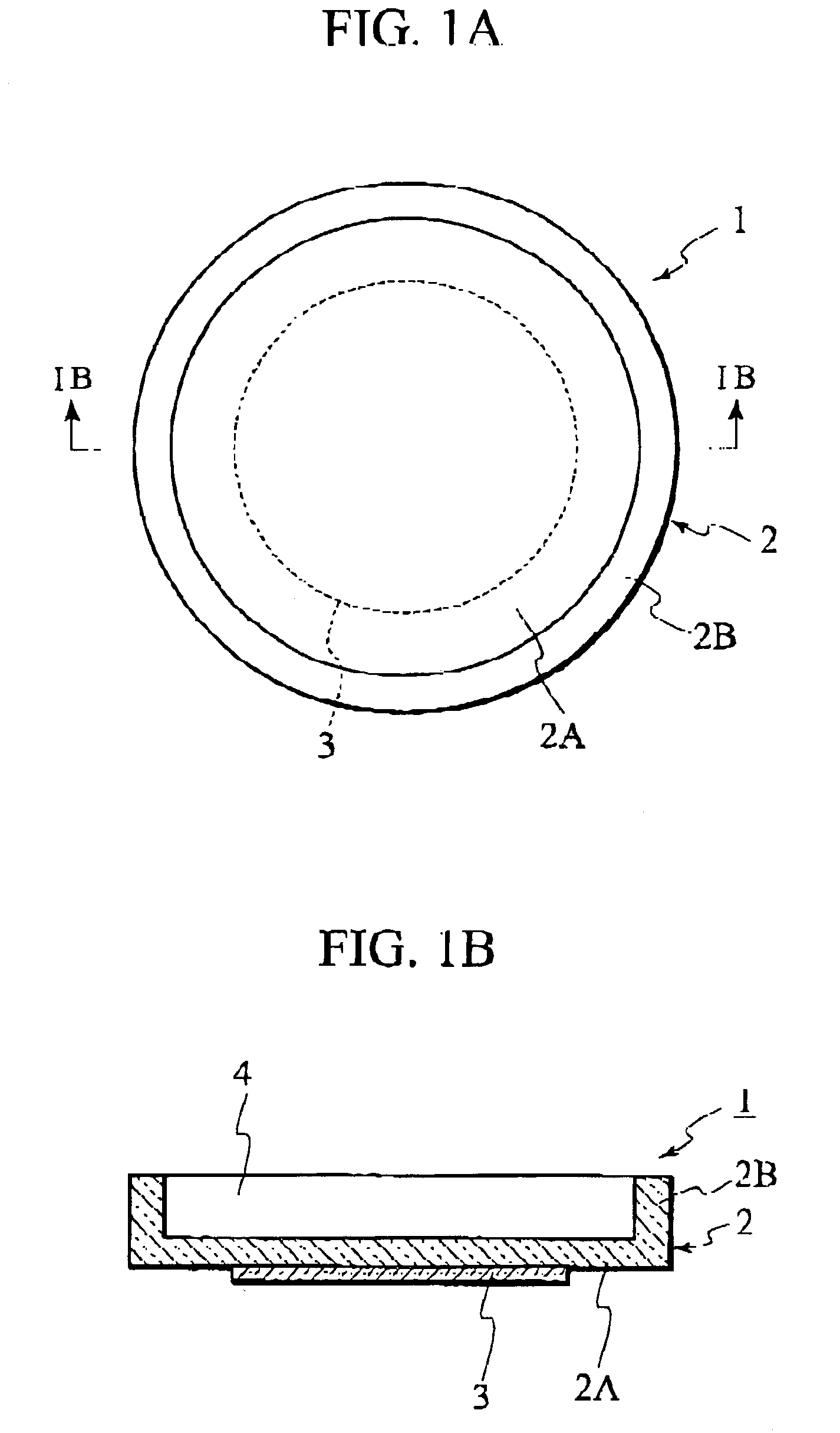
[0049]A first embodiment of the present invention will be described with reference to FIGS. 1A and 1B.

[0050]A reaction cell 1 according to this embodiment comprises a vessel-like cell main body 2 and a circular piezoelectric / electrostrictive oscillator 3 which is provided on the underside (outside surface) of a bottom portion of the cell main body 2. It is to be noted that, although details of the piezoelectric / electrostrictive oscillator 3 are not illustrated in the drawings, the piezoelectric / electrostrictive oscillator 3 has a sandwiched structure wherein a dielectric material member is sandwiched between an upper electrode and a lower electrode. In the cell main body 2, a circular bottom plate portion 2A and a circumferential wall portion 2B which rises from a circumferential edge of the bottom plate portion 2A to thereby surround the bottom plate portion 2A are integrally formed using, for example, zirconia. In the reaction cell 1 having that structure, a space which is surroun...

second embodiment

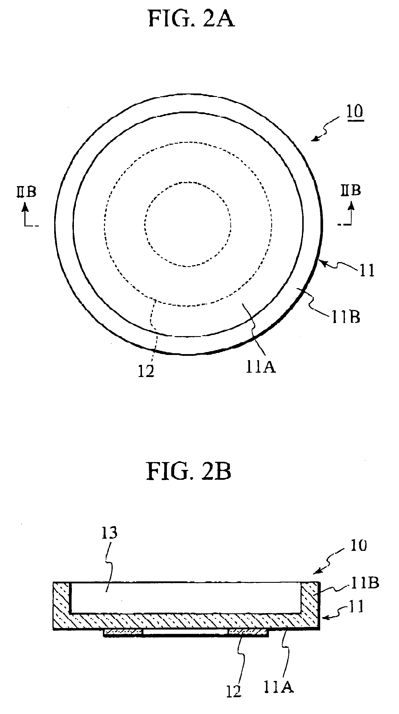
[0055]A second embodiment of the present invention will now be described with reference to FIGS. 2A and 2B.

[0056]A reaction cell 10 according to this embodiment comprises a vessel-like cell main body 11 and an annular piezoelectric / electrostrictive oscillator 12 which is provided on the underside of a bottom portion of the cell main body 11.

[0057]In the cell main body 11, a circular bottom plate portion 11A and a circumferential wall portion 11B which rises from a circumferential edge of the bottom plate portion 11A to thereby surround the bottom plate portion 11A are integrally formed using, for example, optical transmissive alumina. In the reaction cell 10 having that structure, a space which is surrounded by the circumferential wall portion 11B on the bottom plate portion 11A constitutes a solution accommodation space 13. Incidentally, the diameter of the solution accommodation space 13 of the reaction cell 10 can suitably be set to a value falling within a range of from several ...

third embodiment

[0060]A third embodiment of the present invention will be described with reference to FIGS. 3A and 3B.

[0061]A reaction cell 20 according to this embodiment comprises a vessel-like cell main body 21 and a circular piezoelectric / electrostrictive oscillator 22 which is provided within the cell main body 21. It is to be noted that, although the details of the piezoelectric / electrostrictive oscillator 22 are not illustrated, the piezoelectric / electrostrictive oscillator 22 has a sandwiched structure wherein a dielectric material member is sandwiched between an upper electrode and a lower electrode. The cell main body 21 is constructed of a circular bottom plate portion 21A and a circumferential wall portion 21B which rises from a circumferential edge of the bottom plate portion 21A to thereby surround the bottom plate portion 21A. And the bottom plate portion 21A and the circumferential wall portion 21B are integrally formed, the bottom plate portion 21A being formed of, for example, opt...


PUM

PropertyMeasurementUnit
temperatureaaaaaaaaaa
piezoelectric/electrostrictiveaaaaaaaaaa
optical transmissivityaaaaaaaaaa

Abstract

A reaction cell is provided with a vessel-like cell main body and a circular piezoelectric / electrostrictive oscillator fixed to an outside of a bottom surface of the cell main body. The cell main body includes a circular bottom plate portion and a circumferential wall portion which rises from a circumferential edge of the bottom plate portion so as to thereby surround the bottom plate portion. The bottom plate portion and the circumferential wall portion are integrally formed from ceramics. A solution accommodation space is formed above the bottom plate portion and is partially enclosed by the circumferential wall portion. The piezoelectric / electrostrictive oscillator is concentrically adhered to the outside of the bottom surface of the cell main body.

Description

BACKGROUND OF THE INVENTION[0001]1. Field of the Invention[0002]The present invention relates to a reaction cell and, more specifically, to a reaction cell in which a biochemical reaction, such as an enzyme reaction or nucleic acid hybridization, proceeds, and a method of using the reaction cell to carry out and observe chemical reactions.[0003]2. Description of the Related Art[0004]Conventionally, detecting a degree of a reaction or identifying a characteristic of a sample, the nature of which is unknown, is achieved by receiving the sample into a reaction cell and, after the passage of a prescribed reaction length of time, carrying out calorimetric analyses or the like.[0005]Hybridization between complementary nucleic acid strands is an effective method for detecting and identifying genetic materials. The hybridization reaction is a chemical technique wherein two nucleic-acid strands having complementary bases, such as the strands forming molecules of DNA, are bonded to each other...

Claims


Application Information

Patent Timeline
Patent Type & Authority Patents(United States)
IPC IPC(8): B01L3/00G01N29/00B01F11/02G01N35/02C12M1/00G01N11/16G01N33/543H01L41/09
CPCB01F11/0266B01L3/5085G01N11/16G01N33/54393B01L2300/0627B01L2300/0803B01L2400/0439B01F31/86
Inventor TAKEUCHI, YUKIHISAYOSHIDA, YASUKOHIROTA, TOSHIKAZU
Owner NGK INSULATORS LTD
Why Eureka
Try Eureka