
High-efficiency cement mixing device for construction sites
A construction site and mixing device technology, which is applied in cement mixing devices, clay preparation devices, liquid ingredient supply devices, etc., can solve the problems of low mixing efficiency, save materials and funds, improve efficiency, and prolong service life.
- Summary
- Abstract
- Description
- Claims
- Application Information
AI Technical Summary
Problems solved by technology
Method used
Image

Examples
Embodiment 1
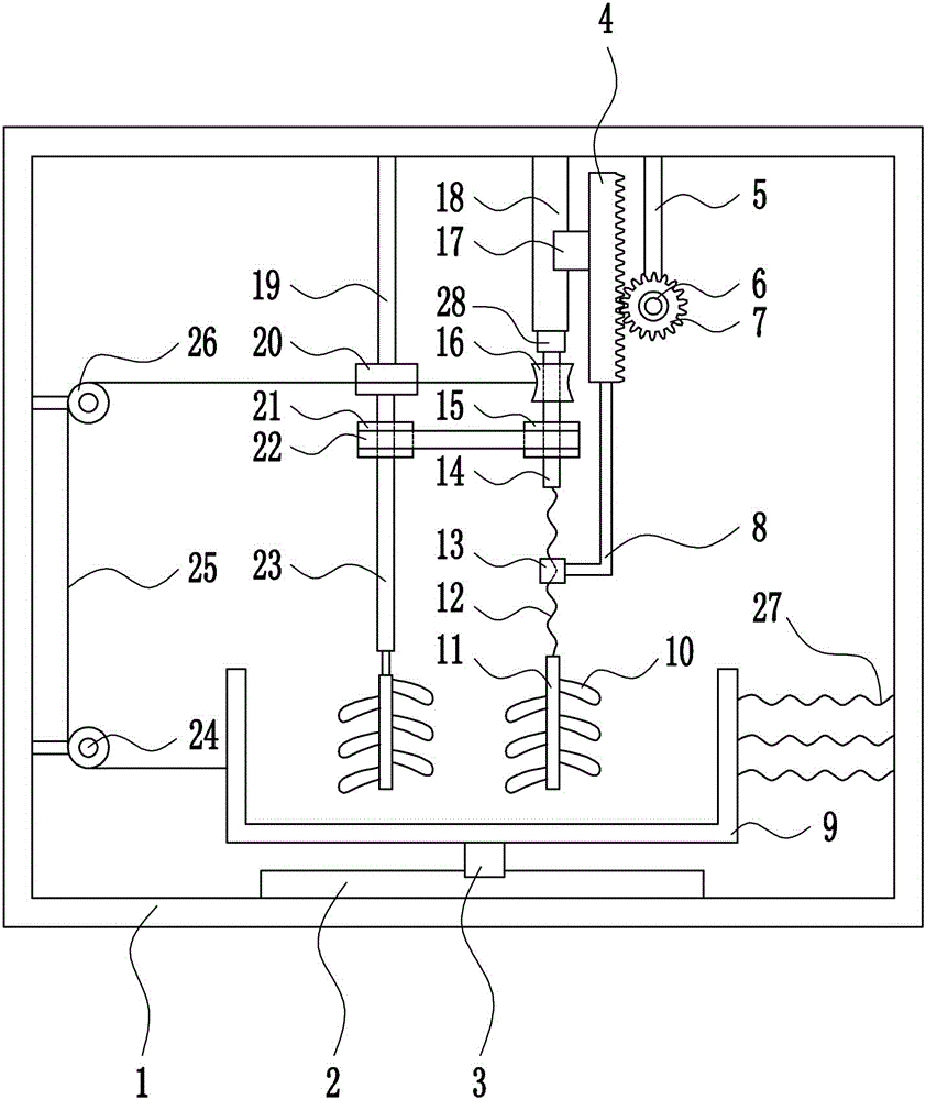
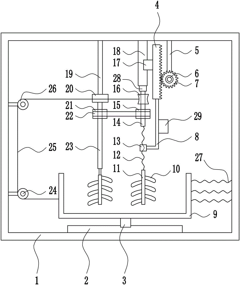
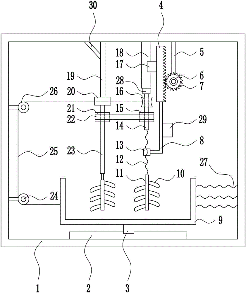
[0031] A high-efficiency cement mixing device for a construction site, such as Figure 1-5As shown, it includes a box body 1, a first slide rail 2, a first slider 3, a rack 4, a second connecting rod 5, a rotating motor 6, a gear 7, a support rod 8, a placement groove 9, blades 10, a stirring Rod 11, screw mandrel 12, nut 13, second rotating shaft 14, first pulley 15, reel 16, second slider 17, second slide rail 18, first connecting rod 19, first bearing seat 20, the first Two pulleys 21, flat belt 22, first rotating shaft 23, first fixed pulley 24, stay cord 25, second fixed pulley 26, spring 27 and second bearing seat 28; the bottom of the box body 1 is provided with the first slide rail 2 , the first slide rail 2 is provided with a first slider 3, the top of the first slider 3 is provided with a placement groove 9, the right wall of the placement groove 9 is provided with a spring 27, the right end of the spring 27 is connected with the inner right wall of the box body 1, a...
PUM
| Property | Measurement | Unit |
|---|---|---|
| depth | aaaaa | aaaaa |
| length | aaaaa | aaaaa |
| width | aaaaa | aaaaa |
Abstract
Description
Claims
Application Information