Novel multi-functional conveyor belt tension control device

A belt tension and control device technology, applied in conveyors, transportation and packaging, etc., can solve the problem that the belt can no longer adjust the looseness, and achieve the effect of improving operability

Inactive Publication Date: 2018-03-23
浙江省柯桥中学
View PDF0 Cites 0 Cited by
  • Summary
  • Abstract
  • Description
  • Claims
  • Application Information

AI Technical Summary

Problems solved by technology

[0002] In the development of modern industry, belts have become an indispensable part, and the use of belts is becoming more and more extensive. However, after the general belt is installed, the looseness cannot be adjusted.

Method used


Image

  • Novel multi-functional conveyor belt tension control device

Examples


Embodiment Construction

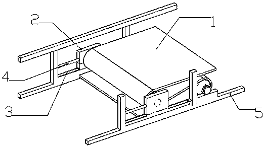
[0011] Please refer to the attached figure 1 , The present invention is a novel multifunctional conveyor belt tension control device, which is composed of 1 belt, 2 moving plates, 3 sliding tracks, 4 struts, and 5 bottom bars.

[0012] Wherein, the belt 1 is located in the center of the device, the moving plate 2 has two pieces, which are respectively located on both sides of the device, the sliding track 3 is located under the moving plate, and the strut 4 is located on the left side of the moving plate 2. Bottom bar 5 is located at the bottom of the device.

[0013] A sliding track 3 is installed below the moving plate 2, and the moving plate 2 is composed of two iron plates.

[0014] The strut 4 is installed on the bottom bar 5 , and the top of the strut 4 is connected with the moving plate 2 .

[0015] During the operation of the novel multi-functional conveyor belt tension control device of the present invention, the looseness of the belt can be adjusted by adjusting th...


PUM


Abstract

The present invention relates to a novel belt tension control device for a multifunctional conveyor, which comprises a belt, a moving plate, a sliding track, a support rod and a bottom bar; wherein, the belt is located in the center of the device, and the moving plate has two pieces, respectively On both sides of the device, the sliding track is located under the moving plate, the support rod is located on the left side of the moving plate, and the bottom bar is located at the bottom of the device. The novel belt tension control device of the present invention has the advantages of convenient operation, adjustable looseness, good operability and the like.

Description

technical field [0001] The invention relates to the field of tension control, in particular to a novel multifunctional conveyor belt tension control device. Background technique [0002] In the development of modern industry, belts have become an indispensable part, and the use of belts is becoming more and more extensive. However, after the general belt is installed, the looseness cannot be adjusted. [0003] Therefore, in order to solve the above technical problems, it is indeed necessary to provide a new belt tension control device with convenient operation, high transport efficiency and good operability to overcome the defects in the prior art. Contents of the invention [0004] In order to solve the above problems, the purpose of the present invention is to provide a new type of belt tension control device which is easy to operate, can adjust the looseness, and has good operability. [0005] In order to achieve the above object, the technical solution adopted by the ...

Claims


Application Information

Patent Timeline
Patent Type & Authority Applications(China)
IPC IPC(8): B65G23/44
CPCB65G23/44
Inventor 孙佳浩
Owner 浙江省柯桥中学
Why Eureka
Try Eureka