A Probe of Variable Stiffness Contact Micro-nano Coordinate Measuring Machine

A coordinate measuring machine and stiffness technology, applied in the field of precision probes, can solve the problems of repeated accuracy of damaged probe systems, piezoelectric driver errors, false triggering, etc., and achieve compact spatial arrangement, compact stiffness adjustment, and reduced measurement. force effect

Active Publication Date: 2020-04-07
ANHUI UNIV OF SCI & TECH
View PDF7 Cites 0 Cited by
  • Summary
  • Abstract
  • Description
  • Claims
  • Application Information

AI Technical Summary

Problems solved by technology

The existing probes have the following problems: 1. The large contact force between the probe and the workpiece will cause damage to the workpiece with a soft surface; 2. The attractive force between the probe and the workpiece will damage the repeatability of the probe system; 3. Inertial force may cause certain false triggers; 4. The stiffness of the probe system is difficult to achieve isotropy; 5. The three-beam suspension form of the variable stiffness probe that has been proposed has very strict requirements on machining accuracy; 6. The force exerted by the electric drive is different, resulting in errors, and it is difficult to effectively compensate for processing defects; 7. When using capacitive or optical sensors, the layout space is insufficient

Method used


Image

  • A Probe of Variable Stiffness Contact Micro-nano Coordinate Measuring Machine
  • A Probe of Variable Stiffness Contact Micro-nano Coordinate Measuring Machine
  • A Probe of Variable Stiffness Contact Micro-nano Coordinate Measuring Machine

Examples


Embodiment Construction

[0017] In order to make the technical solutions and advantages of the present invention clearer, the present invention will be further described below in conjunction with the accompanying drawings and embodiments. It should be understood that the specific embodiments described here are only used to explain the present invention, not to limit the present invention.

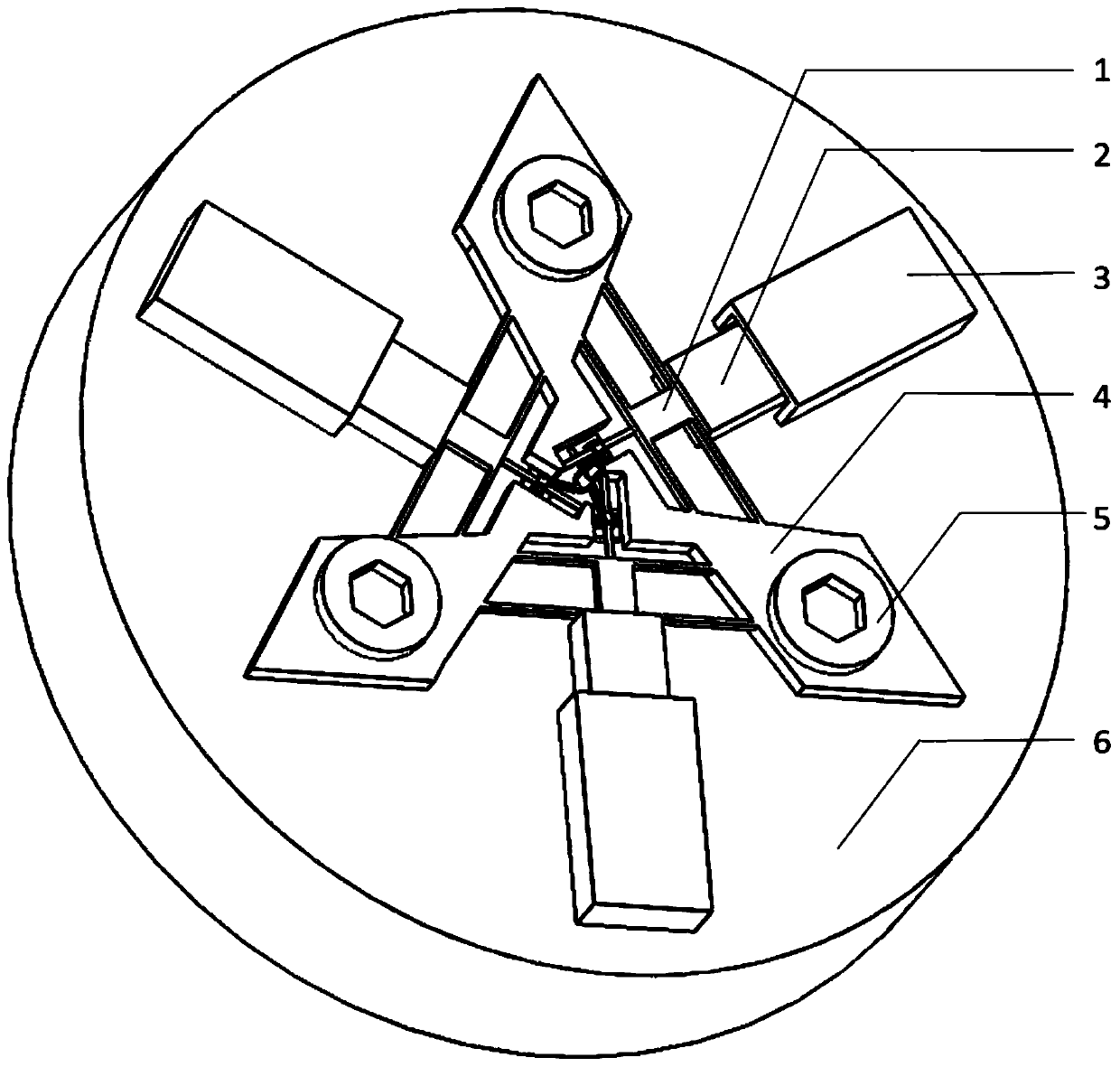
[0018] see figure 1 , figure 2 , image 3 , Figure 4 .

[0019] figure 1 It is a schematic diagram of the front structure of the present invention.

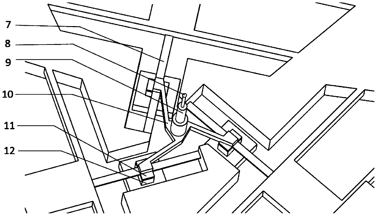
[0020] figure 2 It is a partial structure schematic diagram of the present invention.

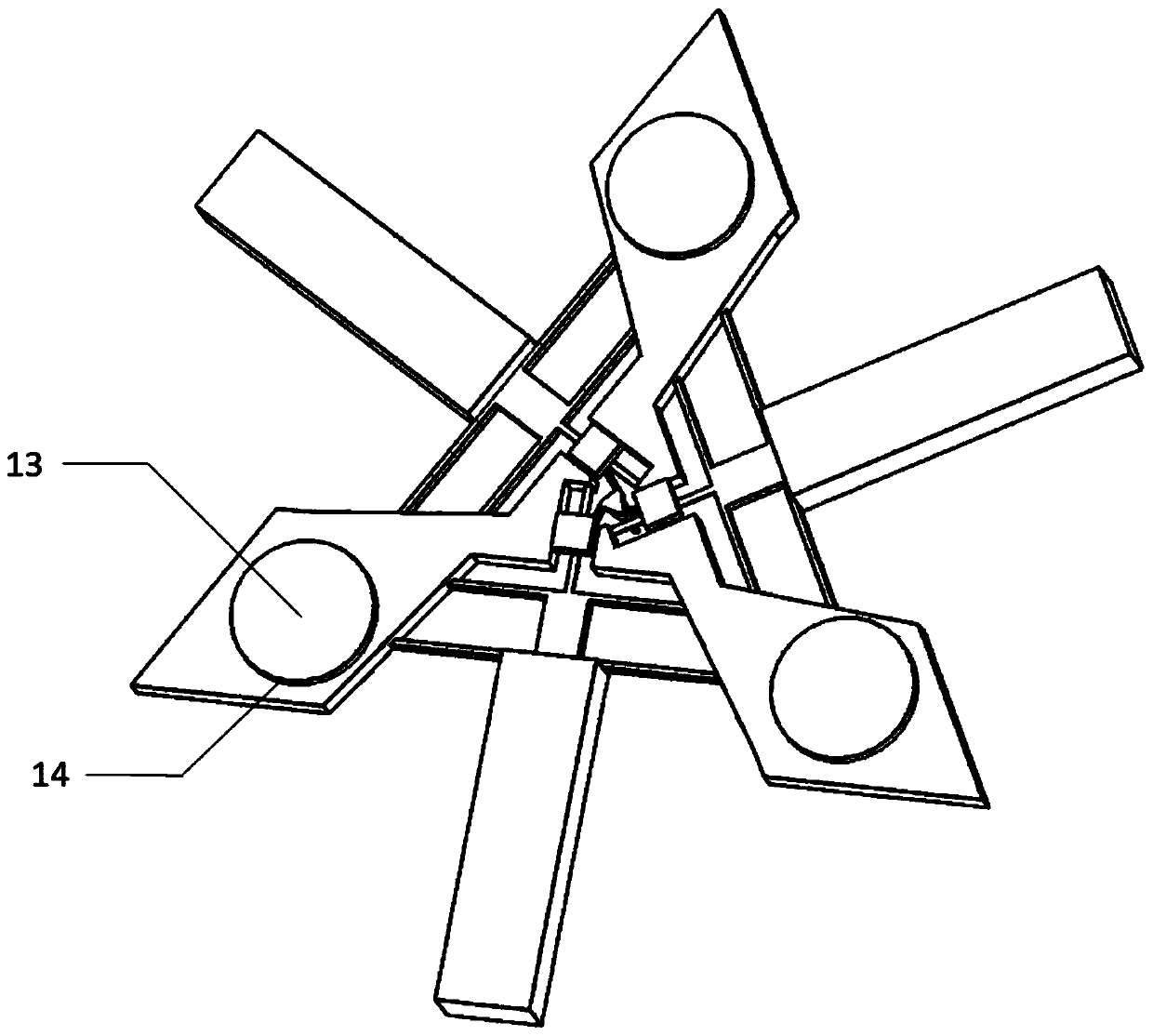
[0021] image 3 It is a schematic diagram of the back structure of the present invention.

[0022] Figure 4 It is a working schematic diagram of the present invention.

[0023] It includes an elastic sensitive beam 7, a central connecting body 10, a "crane"-shaped frame 4, an "I"-shaped compliance mechanism 1, a capacitor upper plate 11, a capacitor lower plate 12, a...


PUM


Abstract

The invention relates to a variable-stiffness contact micro-nano coordinate measuring machine probe which is characterized in that the variable-stiffness contact micro-nano coordinate measuring machine probe comprises elastic sensitive beams, a central connector, a crane-shaped frame, an H-shaped flexible mechanism, a capacitor upper pole plate, a capacitor lower pole plate and a worktable; the inner end of the elastic sensitive beam is fixed to the head part of the crane-shaped frame; the outer end of the elastic sensitive beam is fixed to the inner end of the midpoint of the H-shaped flexible mechanism; the end of the central connector is fixed to the midpoint of the elastic sensitive beam; two sides of the H-shaped flexible mechanism are fixed to the crane-shaped frame; the capacitor upper pole plate is fixed to the lower surface of the end of the central connector; and the capacitor lower pole plate is fixed to the upper end of the worktable. According to the variable-stiffness contact micro-nano coordinate measuring machine probe, through arranging a probe suspension mechanism, probe system stiffness adjustment and compact spatial arrangement structure are realized; through arranging a piezoelectric driver and the elastic sensitive beam, a measuring force in a measuring process is reduced; through arranging the elastic sensitive beams which are uniformly distributed aroundthe axis of the workpiece and the crane-shaped frame, a requirement for mounting symmetry and consistent pressure of the elastic sensitive beam is reduced; and furthermore the variable-stiffness contact micro-nano coordinate measuring machine probe has advantages of simple structure, convenient operation, high economic performance and high practicability.

Description

technical field [0001] The invention relates to a precision measuring head, in particular to a variable stiffness contact type micro-nano coordinate measuring machine measuring head. Background technique [0002] When measuring the surface topography of miniature workpieces, the contact micro-nano coordinate measuring machine needs to use the top of the stepped measuring rod of the probe to contact the measured workpiece, so that the elastic sensitive beam produces a small strain or displacement to calibrate the coordinates of the measured point. At present, most contact micro-nano coordinate machines use probes with fixed stiffness, and the research and application of probes with variable stiffness are still immature. The existing probes have the following problems: 1. The large contact force between the probe and the workpiece will cause damage to the workpiece with a soft surface; 2. The attractive force between the probe and the workpiece will damage the repeatability of...

Claims


Application Information

Patent Timeline
Patent Type & Authority Patents(China)
IPC IPC(8): G01B7/016
CPCG01B7/016
Inventor 李保坤吴耀东刘向阳
Owner ANHUI UNIV OF SCI & TECH
Why Eureka
Try Eureka