Arbitrarily triangular sensor and calibration method thereof

A calibration method and sensor technology, which is applied in the field of sensors and their calibration, can solve problems such as unreasonable structure and difficult installation of sensors, and achieve the effects of eliminating scratches, reducing installation and debugging requirements, and increasing the size range

Inactive Publication Date: 2012-11-21
西安威而信精密仪器有限公司
View PDF0 Cites 0 Cited by
  • Summary
  • Abstract
  • Description
  • Claims
  • Application Information

AI Technical Summary

Problems solved by technology

[0004] The purpose of the present invention is to provide an arbitrary triangular sensor and its verification method to overcome the technical problems of difficult installation and unreasonable structure of the existing profile sensor

Method used


Image

  • Arbitrarily triangular sensor and calibration method thereof
  • Arbitrarily triangular sensor and calibration method thereof
  • Arbitrarily triangular sensor and calibration method thereof

Examples


Embodiment Construction

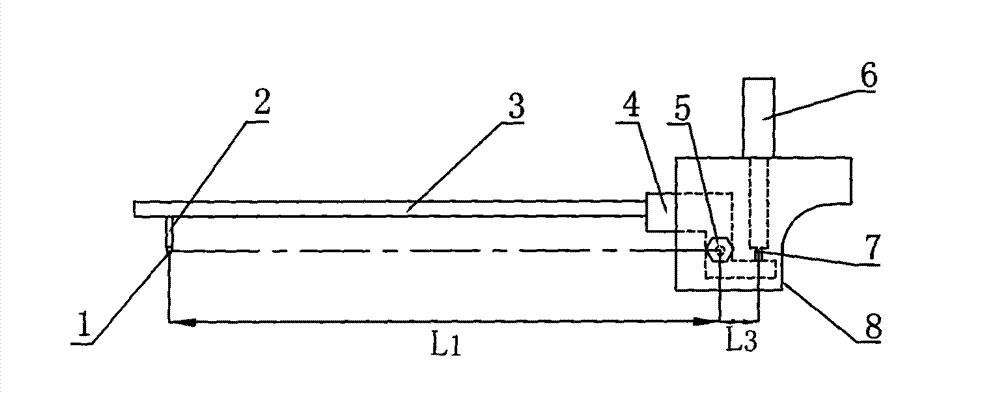
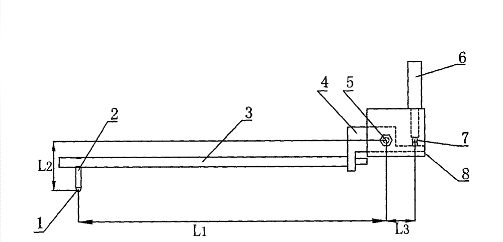
[0026] see figure 1 and figure 2 , an arbitrary triangular sensor involved in the present invention, including a sensor joint block 8, a sensor 6 installed on the sensor joint block 8, an adapter 4 hinged on the sensor joint block 8 through the center of rotation 5, and an adapter 4 arranged on the adapter 4 The measuring rod 3 at one end, the measuring needle 2 arranged at the end of the measuring rod 3 away from the adapter 4; the other end of the adapter 4 is in contact with the sensor contact 7; The rod 3 is parallel and located above the measuring rod 3 . In order to prevent the joint block from colliding with the measured object, it is better to make the bottom surface of the sensor joint block 8 parallel to the horizontal plane and above the measuring rod 3 . In order to change the measurement range so as to realize the measurement of various workpiece ranges, the measuring rod 3 is a plurality of replaceable measuring rods with different lengths.

[0027] A kind of...


PUM


Abstract

The invention discloses an arbitrarily triangular sensor and a calibration method thereof. The arbitrarily triangular sensor comprises a sensor connector block, a sensor, an adaptor, a measuring rod and a probe, wherein the sensor is arranged on the sensor connector block; the adaptor is pivoted on the sensor connector block through a rotary centre; the measuring rod is arranged on one end of theadaptor, the probe is arranged on one end away from the adaptor; the other end of the adaptor is contacted with the sensor contact; and the line connecting the rotary centre and the sensor contact centre is parallel to the measuring rod and above the measuring rod. The calibration method comprises: mounting the sensor, computing a group of variables H corresponding to the centre of the probe, obtaining a group of calibration values, substituting the calibrated parameter values into a program and re-measuring, verifying the accuracy of the measurement, and eliminating the installation errors. The arbitrarily triangular sensor and the calibration method thereof reduce requirements on installation and debugging of the sensor and make operation simpler and more convenient.

Description

technical field [0001] The invention relates to a sensor and a verification method thereof. Background technique [0002] In the traditional profilometer measuring device, during the installation process of the sensor 6 and the measuring rod 3 , higher requirements are put forward for the installation of the sensor 6 . Such as figure 1 As shown, it is necessary to ensure that the center of the probe 1, the center of rotation 5 of the measuring rod 3, and the center of the sensor contact 7 are on the same straight line, and the measuring rod 3 is required to be parallel to the marble work surface, because the installation of the three-point-one-line structure is more difficult. Difficult, it is difficult to ensure the special requirement of three points and one line; on the other hand, its measurement force is relatively large, which is easy to cause measurement scratches on the measured workpiece; at the same time, when replacing the measuring rod 3, it is necessary to re-c...

Claims


Application Information

Patent Timeline
Patent Type & Authority Patents(China)
IPC IPC(8): G01B21/20
Inventor 戴桂秋
Owner 西安威而信精密仪器有限公司
Why Eureka
Try Eureka