Accurate stroke positioning system capable of allowing large deviation
A stroke positioning and precise positioning technology, which is applied in the direction of instruments, measuring devices, and conversion sensor output, etc., can solve the problem that the positioning accuracy and the expansion of the tolerance range cannot be obtained at the same time, and achieve low installation and debugging requirements, low implementation costs, and low structure. simple effect
- Summary
- Abstract
- Description
- Claims
- Application Information
AI Technical Summary
Problems solved by technology
Method used
Image
Examples
Embodiment 1
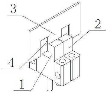
[0040] like image 3 As shown, the present embodiment provides a precise stroke positioning system that allows large deviations, including a code plate 3, a detection window 1 4 and a detection window 2 5; the code plate 3 is provided with a detection window 4 and a detection window for triggering Two gaps 6 of the same width in the second 5, the width of the gap 6 is L5, and the width of the code plate part between the two gaps 6 is L2; The distance is L1, which is the maximum signal boundary value of the two detection windows.
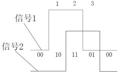
[0041] Different coded signals are formed by the positions between the code plate 3 and the two detection windows, and the travel positioning information of the equipment to be detected is judged by the coded signals.
[0042] In order to effectively trigger the detection window, the position between the code board 3 and the two detection windows must satisfy: (1) L1L5.
[0043] By adjusting the width L2 of the code plate portion between the two no...
Embodiment 2
[0048] On the basis of Embodiment 1, based on the above-mentioned precise stroke positioning system that allows large deviations, the signal detection switch and the code board can be output according to different situations when the detection window 1 4 and / or the detection window 2 5 are triggered. The combination of positions between 3 corresponds to the encoded signal formed.
[0049] Correspondingly, the travel positioning information includes a positioning position status, and the positioning position status includes a precise positioning status, a positioning deviation status, and a limit status of a maximum allowable positioning deviation range. in:
[0050] Determine the precise positioning position signal of the precise positioning state according to the numbered signal data corresponding to the precise positioning state;
[0051] According to the encoded signal data corresponding to the positioning deviation state, the identifiable range position signal of the posi...
Embodiment 3
[0061] The positioning steps realized by the precise stroke positioning system that allows large deviations are as follows:
[0062] First, when the two detection windows are located on the left side of the code board 3 or the right side of the code board 3, it is set to the initial state, that is, the signal state in which the detection windows are not triggered, such as Figure 4 shown;
[0063] When the two detection windows and the code plate 3 move relative to each other, one detection window is blocked, and the other detection window is not blocked and is located at the gap 6, the state at this time is regarded as a positioning deviation state of the stroke detection signal; the positioning deviation In this state, valid positioning position signals can be obtained from the output coded signals, and position signals in precise positioning status can also be distinguished, and the range of allowable positioning deviations can be expanded, such as Figure 5 shown;
[006...
PUM
 Abstract
Description
Claims
Application Information
 - R&D
- Intellectual Property
- Life Sciences
- Materials
- Tech Scout
- Unparalleled Data Quality
- Higher Quality Content
- 60% Fewer Hallucinations
Browse by: Latest US Patents, China's latest patents, Technical Efficacy Thesaurus, Application Domain, Technology Topic, Popular Technical Reports.
© 2025 PatSnap. All rights reserved.Legal|Privacy policy|Modern Slavery Act Transparency Statement|Sitemap|About US| Contact US: help@patsnap.com


