An Optimal Design Method for the Air Inlet Pipeline System of the Oven of a Gravure Printing Machine
An air inlet duct and optimization design technology, applied in computer-aided design, design optimization/simulation, calculation, etc., can solve problems such as uneven wind speed and increased energy consumption of the oven, so as to achieve simple and clear design methods and reduce energy consumption Loss, the effect of improving uniformity
- Summary
- Abstract
- Description
- Claims
- Application Information
AI Technical Summary
Problems solved by technology
Method used
Image

Examples
Embodiment 1
[0070] This embodiment provides an optimal design method for the air inlet duct system of the gravure printing machine oven, which is specifically implemented according to the following steps:
[0071] Step 1: Design the structure of the oven inlet duct system according to the space of the gravure printing machine, the size of the oven body and the selection of the fan, and determine the structure and size of the heater, inlet duct, return duct and lumen, or directly from the enterprise Obtain the structure of the oven inlet duct system to be optimized;
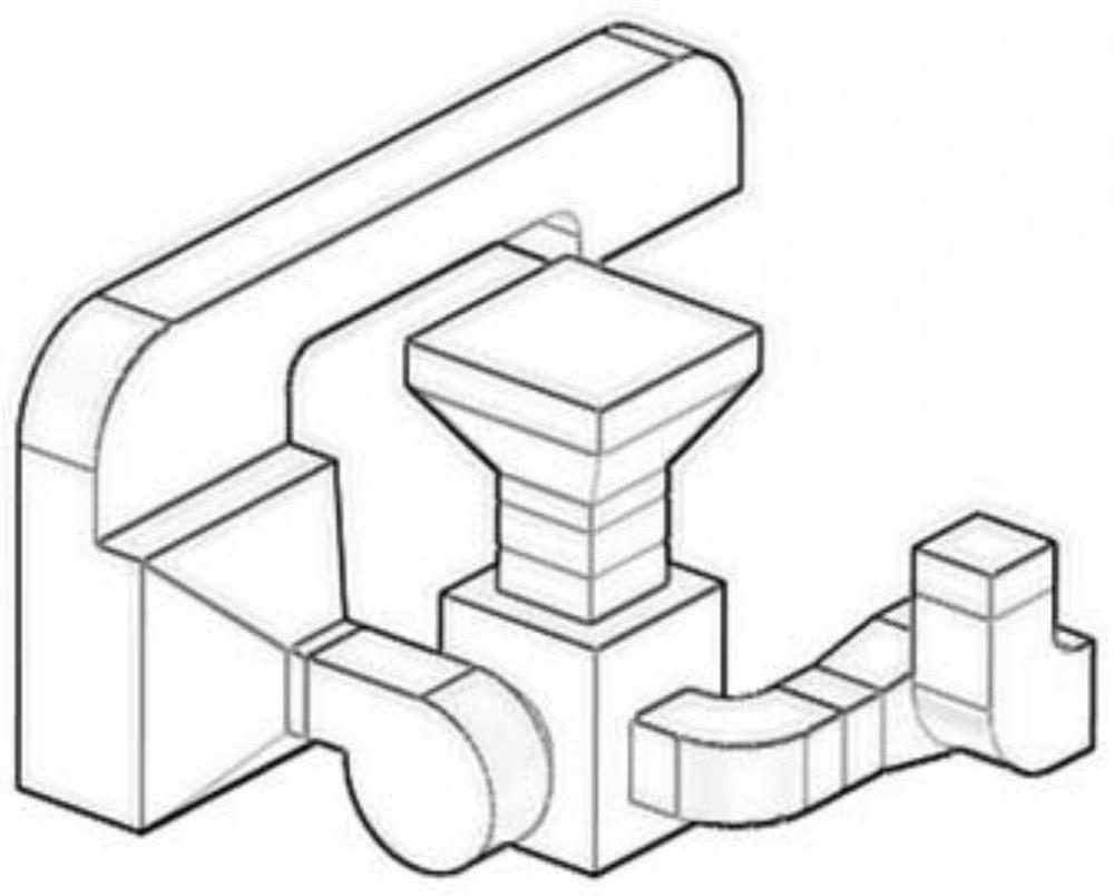
[0072] Step 2: Use 3D design software to model the fluid domain of the air inlet duct system designed in step 1. The model is as follows figure 1 As shown, and then use the grid processing software GAMBIT to discretize the fluid domain;
[0073] Step 3: Use the fluid simulation software to set boundary conditions for the fluid domain discretized in Step 2, including velocity inlet: velocity is 30m / s, pressure outlet: static ...
Embodiment 2
[0082] This embodiment provides an optimal design method for the air inlet duct system of the gravure printing machine oven, which is specifically implemented according to the following steps:
[0083] Step 1: Design the structure of the oven inlet duct system according to the space of the gravure printing machine, the size of the oven body and the selection of the fan, and determine the structure and size of the heater, inlet duct, return duct and lumen, or directly from the enterprise Obtain the structure of the oven inlet duct system to be optimized;
[0084] Step 2: Use 3D design software to model the fluid domain of the air inlet duct system designed in step 1, and then use the grid processing software GAMBIT to discretize the fluid domain;
[0085] Step 3: Use the fluid simulation software to set boundary conditions for the fluid domain discretized in Step 2, including velocity inlet: velocity is 30m / s, pressure outlet: static pressure is 101325pa, wall condition: no-sli...
Embodiment 3
[0093] This embodiment provides an optimal design method for the air inlet duct system of the gravure printing machine oven, which is specifically implemented according to the following steps:
[0094] Step 1: Design the structure of the oven inlet duct system according to the space of the gravure printing machine, the size of the oven body and the selection of the fan, and determine the structure and size of the heater, inlet duct, return duct and lumen, or directly from the enterprise Obtain the structure of the oven inlet duct system to be optimized;
[0095] Step 2: Use 3D design software to model the fluid domain of the air inlet duct system designed in step 1, and then use the grid processing software GAMBIT to discretize the fluid domain;
[0096] Step 3: Use the fluid simulation software Fluent to set boundary conditions for the fluid domain discretized in step 2, including velocity inlet: velocity is 30m / s, pressure outlet: static pressure is 101325pa, wall conditions...
PUM
 Abstract
Description
Claims
Application Information
 - R&D
- Intellectual Property
- Life Sciences
- Materials
- Tech Scout
- Unparalleled Data Quality
- Higher Quality Content
- 60% Fewer Hallucinations
Browse by: Latest US Patents, China's latest patents, Technical Efficacy Thesaurus, Application Domain, Technology Topic, Popular Technical Reports.
© 2025 PatSnap. All rights reserved.Legal|Privacy policy|Modern Slavery Act Transparency Statement|Sitemap|About US| Contact US: help@patsnap.com